Quality 101: Force Gage Basics
Force gages are universal and versatile measuring instruments used across all industries. As its name suggests, a force gage is used to measure the force during a push or pull test. Applications exist in research and development, production and quality laboratory environments.

The load cell, or force sensor, is at the heart of any digital force gage. The load cell is essentially a spring that flexes as force is exerted on it. As the spring flexes, strain gages measure this strain and output a voltage: the greater the force, the greater the strain and, therefore, the greater the voltage output. Through electronics and a microprocessor, this voltage is converted into a force value that is displayed on the instrument.
As opposed to other types of measuring instruments, such as tachometers and coating thickness gages, the bodies of force gages can witness a significant amount of force-in general, up to 1,000 pounds. Force gage housings are, therefore, typically constructed of rugged materials.
Force gages are available in a range of force capacities, reflecting the great number of different products that need to be tested. Test units are most commonly pounds, kilograms or newtons. Various test stands, grips and fixtures are available for use with these instruments, which vary widely based on the sample being tested.
Of principal interest in most applications is the peak force, or maximum observed force, during the test. This metric often is used to determine whether a part is acceptable or not. For instance, an acceptable bag of potato chips may open at between 2 and 3 pounds of force. An acceptable door latch on an automobile may require between 6 and 8 pounds of force to open.
In most testing of manufactured components, it is important that the load is applied axially with respect to the instrument. If not, it is possible that damage can occur to the load cell, or that the displayed force reading may be skewed because of the angle of measurement.
Another point to consider is that a force gage should not be used to measure shock or impact loads. A sudden buildup of force may not be measured very accurately; force gages are most effective at longer duration tests.
Consistent speed is an important though often overlooked factor in force measurement. Because of this, handheld testing is not recommended for most applications. Depending on the test speed, a sample may require a greater or lesser amount of force to achieve the test’s objective. Whatever the speed, it should be consistent so that subsequent tests can be compared according to the same parameters. Numerous standards have been published specifying test speed.
A motorized test stand or manual test stand, particularly hand wheel types, is useful in helping to achieve speed consistency. It also aligns the force gage correctly and usually provides amplefixture mounting holes.

Some other applications require more than just the peak. Laboratory testing often calls for the force profile to be recorded and used to scientifically analyze the behavior of the sample. This is common in materials testing-for example, the testing of metals and plastics-and also in testing assemblies such as bottle caps, sealed pouches and push buttons.
A force gage is a capable instrument that has numerous applications. It can be used for a range of simple peak force measurement, but also can be used in sophisticated test applications requiring scientific analysis of a sample. With proper use, it can yield a wealth of useful data with which quality professionals can quantify the quality of finished products.
A digital force gage is shown in a tensile testing application mounted to a motorized test stand. Source: Mark-10
What is a Force Gage?
Although mechanical and digital force gages are both widely used, the focus here is on digital force gages, which are gradually replacing most mechanical force gages in the field. A digital force gage is essentially a handheld instrument that contains an integral load cell, electronics and display.The load cell, or force sensor, is at the heart of any digital force gage. The load cell is essentially a spring that flexes as force is exerted on it. As the spring flexes, strain gages measure this strain and output a voltage: the greater the force, the greater the strain and, therefore, the greater the voltage output. Through electronics and a microprocessor, this voltage is converted into a force value that is displayed on the instrument.
As opposed to other types of measuring instruments, such as tachometers and coating thickness gages, the bodies of force gages can witness a significant amount of force-in general, up to 1,000 pounds. Force gage housings are, therefore, typically constructed of rugged materials.
Force gages are available in a range of force capacities, reflecting the great number of different products that need to be tested. Test units are most commonly pounds, kilograms or newtons. Various test stands, grips and fixtures are available for use with these instruments, which vary widely based on the sample being tested.
Of principal interest in most applications is the peak force, or maximum observed force, during the test. This metric often is used to determine whether a part is acceptable or not. For instance, an acceptable bag of potato chips may open at between 2 and 3 pounds of force. An acceptable door latch on an automobile may require between 6 and 8 pounds of force to open.
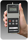
Force gages are compact but capable instruments that can be used for a wide range of push and pull testing requirements. Source: Mark-10
How to Use a Force Gage
Proper use of a force gage is simple, but failure to follow some basic guidelines can result in damage to the instrument and incorrect or inconsistent results.In most testing of manufactured components, it is important that the load is applied axially with respect to the instrument. If not, it is possible that damage can occur to the load cell, or that the displayed force reading may be skewed because of the angle of measurement.
Another point to consider is that a force gage should not be used to measure shock or impact loads. A sudden buildup of force may not be measured very accurately; force gages are most effective at longer duration tests.
Consistent speed is an important though often overlooked factor in force measurement. Because of this, handheld testing is not recommended for most applications. Depending on the test speed, a sample may require a greater or lesser amount of force to achieve the test’s objective. Whatever the speed, it should be consistent so that subsequent tests can be compared according to the same parameters. Numerous standards have been published specifying test speed.
A motorized test stand or manual test stand, particularly hand wheel types, is useful in helping to achieve speed consistency. It also aligns the force gage correctly and usually provides amplefixture mounting holes.
Pull-off force testing of a toy component is shown here using a force gage with test stand and grips. Source: Mark-10
Interpreting the Results
As discussed previously, the peak force often is considered the most important determinant in a force test. In such applications, typical for production environments, a number of peak forces from a batch may be collected and analyzed. It is common to set upper and lower acceptable control limits and generate statistics from these data.Some other applications require more than just the peak. Laboratory testing often calls for the force profile to be recorded and used to scientifically analyze the behavior of the sample. This is common in materials testing-for example, the testing of metals and plastics-and also in testing assemblies such as bottle caps, sealed pouches and push buttons.
A force gage is a capable instrument that has numerous applications. It can be used for a range of simple peak force measurement, but also can be used in sophisticated test applications requiring scientific analysis of a sample. With proper use, it can yield a wealth of useful data with which quality professionals can quantify the quality of finished products.
Looking for a reprint of this article?
From high-res PDFs to custom plaques, order your copy today!


