Practical Multisensor Metrology
Measuring systems for manufacturing quality control can offer combinations of sensor technologies so those systems can do more thorough measurements of even the most complex parts. Selecting the sensor to use for a particular measurement must be based on its capabilities and the characteristics of actual parts to be measured.
There are now video measuring machines with touch probes, coordinate measuring machines (CMMs) with cameras, both video measuring machines and CMMs with lasers, and other combinations of sensors on measuring machines.
Manufacturers of these multisensor measurement machines emphasize the performance advantages of their systems, assuming operators will understand how to put those sensors to practical use. A skeptic might be concerned about the complexity of those systems and whether their additional measurement capabilities outweigh those concerns. As part of the evaluation of any measurement system it is important to understand what those sensors actually do to understand how using a portfolio of them on a single measuring machine can be beneficial.

This benchtop multisensor measurement system is measuring metal, plastic and glass parts with multiple sensors. Source: OGP
Manufacturing Metrology
Manufacturers today are under pressure to reduce costs while simultaneously improving product quality. The bar of customer quality expectations is continually rising, but customers do not want to pay more for that improved quality. These contradictory requirements put pressure on manufacturers to streamline their processes and make them more efficient. Although reducing the number of measurements on each part might increase throughput, doing so risks meeting the expected quality requirements. In fact, it is not unusual to require more measurements at ever-tighter tolerances to ensure expected quality of the final product.Moving a part from measuring device to measuring device can lengthen the overall manufacturing process, as well as lead to bottlenecks from queuing parts at multiple stations. Multisensor measurement systems attempt to resolve these conflicting requirements by allowing manufacturers to perform more measurements in a single setup on a single machine.
Multisensor means more than one sensor or multiple sensors. As commonly used, the sensor is the technology used to acquire data points from the part. Typical sensors include video, or vision, touch probe and laser. In a multisensor system, there is a primary sensor technology-the basis for the machine design. The size and attributes of the measured part determine the appropriate primary sensor. Other sensors are added to the machine. How well such systems work as multisensor systems depends on how well all of the sensor technologies are integrated. Of equal importance is how well the system software controls each sensor and uses its data for total dimensional characterization of the part.
Someone unfamiliar with multisensor metrology might think that it means a machine that can use more than one sensor to measure a particular dimension or a coordinate, like some sort of measurement validation.
What multisensor measurement means is that the system can derive more measurements of a part from the analysis of data from its different sensors, each capable of measuring something the others cannot, or cannot do as well.
There is good reason for using multiple sensors. The wide range of gages, inspection and measurement systems exists because each excels at particular functions, or groups of functions. At the same time, different technologies might be capable of measuring a particular parameter, but each does it to a different level of precision. Or, the choice of measuring device might depend on where in the process the measurement is needed, the size of the part and the measurement tolerance.

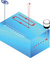
Video measurement can provide dimension ‘d’ between two holes in the same plane. Source: OGP
One Sensor Technology at a Time
Stepping away from the continuum of measuring devices that range from simple hand gages to massive gantry CMMs, consider multisensor video measuring systems to explain how to use multiple sensors. In these systems, vision measurement is the primary sensor technology.Video, or vision, measuring systems excel at measuring edges. By properly illuminating a part, magnifying and focusing that image with a camera, image analysis software can determine numerous edge points with a high degree of precision and repeatability. Because those edge points are derived from a magnified image of the part, they are known to a higher precision than would be possible from direct measurement with any other technique. Measured edges may be barely visible to the naked eye, yet repeatedly measured with a vision system because they are magnified and illuminated to maximize contrast from the surrounding material. In fact, edges with no physical features, such as the boundary between areas on a part of different colors, can only be measured with vision technology.
Although some parts have edges that fit within the image area of a lens system, another attraction of a video measuring system is that it can determine the coordinates of edge points at high precision on edges separated by large distances. For example, systems that use motorized stages with high-resolution scales can verify the distance between the edges of holes 500 millimeters apart or more with microns of accuracy. And their part programs will repeat those measurements automatically for every part that is placed on the machine.
It may be easy to visualize measurement of holes and edges that all lie in a plane, but that is not a limitation. Machines designed with similar X, Y and Z resolutions can measure edges that lie anywhere within the Z-travel range of the machine.

Video measurement systems with 3-D software and Z-axis scales can do more complex measurements such as dimension ‘d’ between holes in two planes. Source: OGP
Most lasers work by monitoring the location of a laser spot on the surface of a part by noting where it focuses, or its change in position on a sensor as a function of changes in surface height. With its small focal spot, laser data can represent a single point on a surface. Scanning the laser across the part while sampling its detector can provide accurate surface contour data of points at user-specified distances from one another.
Touch trigger probes acquire data from physical contact with the part. Probes can approach the part from almost any direction. For example, points from a top surface can be fit to a plane and compared to points from a vertical surface to verify those surfaces are perpendicular. The walls of a bore can be measured at varying depths to verify cylindricity. The depth of a bore that might be beyond the video or laser depth of focus can be measured with a long stylus, and styli can be changed during a measurement routine by accessing them from a change rack.
Shown is an example of part features that can be scanned with video, laser and touch-probe technologies. Source: OGP
Doing More with Each Sensor
It is important to understand that each of the sensor technologies mentioned is still evolving. Consider scanning. It is possible for each of these sensor technologies to scan a part. Some video systems can follow edges that extend beyond the optical field of view, automatically controlling stage positions as the edge contour changes, scanning the perimeter of the most complex parts. Lasers can provide single focus points, or they scan in a line or other pattern, or in a series of parallel lines to provide a 3-D map of a surface. Touch probes can provide single point measurements, but models are available that can scan across a surface, even a surface perpendicular to the one scanned by a laser, sampling data points as they move.Showing scans by these three different sensors helps explain the value of multisensor measurement. Video scans edges as viewed from the optical axis. Lasers scan across surfaces from which the laser light is reflected. Scanning touch probes scan along surfaces perpendicular to those accessible for video or laser.
Of course, video can profile a surface, but not as accurately as a laser can. A laser can find edges, but only if the edge has a physical height change-and then only as it crosses the edge while scanned. Neither video nor laser can scan the vertical walls of a part, although a part mounted in a rotary can bring those surfaces into position so they can be scanned. A scanning touch probe with the correct stylus can scan around the walls of a part, but is not good for edge locating. Put them all together and the strengths of each combines to give more useful information about a measured part than a single sensor system can provide.
The choice of sensors and the decision when to use them depends on understanding what those sensors do best, the dimensions that need to be verified, and the sizes and characteristics of parts to be measured. Make sure the manufacturing tolerances are appropriate for proper fit and finish, and measure accordingly. Using the best sensor for each measurement will boost overall efficiency. Q
Tech Tips
Looking for a reprint of this article?
From high-res PDFs to custom plaques, order your copy today!


