Thermography of Turbine Airfoils
Until recently, thermography was limited to a secondary, qualitative role in airfoil QA. However, advances in the technology have given rise to thermographic QA systems that are capable of replacing traditional technologies.
 The modern gas turbine airfoil is a marvel of modern engineering, material and manufacturing science. Both airborne and land-based blades and vanes must operate under extreme thermal and mechanical stresses in the hot section of the engine, and must be manufactured to the most exacting tolerances. Manufacture of a turbine airfoil is a multistep process that typically involves casting, coating and machining operations. The airfoils are formed by an investment casting process, where ceramic cores form a labyrinthine network of cooling channels in the mold. Once cast, cooling holes are then machined into the airfoil surfaces followed by application of a Thermal Barrier Coating (TBC).
The safety-critical nature of an aircraft turbine or the dire economic consequences of a power-plant outage make quality assurance (QA) a primary concern for the entire supply chain, since inspections must be performed at every stage of the manufacturing process. Each stage presents unique challenges. For example, in the casting process, the ceramic cores may shift from their intended positions, or core residue may become embedded in the cooling channels. In the coating process, TBC thickness and adhesion to the metal must be confirmed. In machining, cooling holes may be formed incorrectly or become blocked by core debris. At present, each of these challenges is addressed by a separate inspection technology, making the QA process a complex matrix of inspections that are performed serially, involving a variety of equipment, personnel and procedures. The net result is time-consuming and expensive.
The serial application of different inspection methods and the laborious nature of some techniques can create significant logjams in production throughput. For example, the inspection of airfoils for blocked cooling holes is required for every blade in an aircraft engine. Each blade may have hundreds of tiny cooling holes. Currently, the standard inspection methods in the industry are pin-gauge testing, where an inspector manually inserts a fine wire into each hole, or alternately, a flow test, where a fluid is forced through the blade and an inspector visually observes the spray pattern for anomalies. The pin test is labor intensive and prone to operator fatigue, and both methods are subjective.
The potential of thermography for non-contact, single-side, wide-area Nondestructive Testing (NDT) has been widely recognized since the introduction of the first IR cameras in the late 1960s. Although early efforts in thermography were largely qualitative, and highly dependent on subjective interpretation of image results, modern thermography systems are widely used in manufacturing and in-service applications in the aerospace, power generation and automotive industries. Applications range from inspection of solar cell arrays in space satellites to QA of composite aircraft structures.

Flash Thermography is widely used in both coating and casting inspections. The airfoil surface is heated with a pulse of light lasting a few milliseconds. As heat from the surface diffuses into the metal, the surface cools in a predictable manner. However, the presence of an interface between materials (e.g. coating–metal, metal–air), flaws (e.g. unbonds or delamination) or internal structure (e.g. channel walls, turbulators, pedestals) disrupts the normal cooling behavior. The thermographic signal reconstruction (TSR) method is widely used to recover details of the internal structure, and allowing measurement of TBC or airfoil wall thickness with a degree of accuracy that is comparable to UT or eddy current methods.
Various forms of Flow Thermography have historically been used for qualitative inspection of flow through cooling passages and holes. In the simplest implementation, the operator views the IR image as a hot or cold fluid (typically water or air) is forced through the internal cooling channels. Blockages appear as discontinuities in the surface temperature along the channel, although partial blockages may be difficult to detect reliably. A new generation of flow thermography systems provides far greater sensitivity and reliability for both channel and hole blockage. These systems can be fully automated and are gradually replacing manual pin test methods.
Although Vibrothermography was originally discovered in the late 1970s, it has only recently come into its own as an NDT method that is particularly well-suited to detection of cracks in airfoils. Unlike other active thermography techniques where the entire component is heated or cooled, vibrothermography injects high-energy acoustic energy, typically in the 10-40 kHz range, into the part using an ultrasonic horn. Heating only occurs at a closed crack due to the rubbing action of the crack faces. Extremely small cracks can be detected in a few seconds, making the technique an attractive alternative to penetrant methods.
Thermography offers a number of advantages when compared to traditional airfoil inspection methods. It is relatively fast (most inspections can be performed in a few seconds), automation-friendly and does not require contact or surface preparation of the part. It also provides an assessment of heat transfer performance, which is the essential function of the airfoil, while ultrasound, radiography and manual blockage detection provide only structural information.
Looking toward the future, thermography shows great promise for inspection of the next generation of advanced turbine components, which are based on ceramic matrix composites (CMC). Active thermography presents several advantages over other conventional NDT methods such as ultrasound and X-ray for applications including porosity and wall thickness measurement, and detection of density variations and foreign object debris (FOD). In large part, this is due to the non-contact, non-invasive and curvature tolerant attributes of active thermography in conjunction with advances made in physics-based signal processing and material characterization. NDT
The entire suite of airfoil inspections can be performed using thermography.
Thermography is relatively fast, automation-friendly and does not require contact or surface preparation of the part.
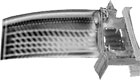
Flash thermography using Thermographic Signal Reconstruction used to accurately measure wall thickness of turbine blade. Source: Thermal Wave Imaging Inc.
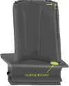
Flash thermography reveals MCrAlY coating disbonds (yellow) in airfoil/platform transition and trailing edge. Source: Thermal Wave Imaging Inc.
The safety-critical nature of an aircraft turbine or the dire economic consequences of a power-plant outage make quality assurance (QA) a primary concern for the entire supply chain, since inspections must be performed at every stage of the manufacturing process. Each stage presents unique challenges. For example, in the casting process, the ceramic cores may shift from their intended positions, or core residue may become embedded in the cooling channels. In the coating process, TBC thickness and adhesion to the metal must be confirmed. In machining, cooling holes may be formed incorrectly or become blocked by core debris. At present, each of these challenges is addressed by a separate inspection technology, making the QA process a complex matrix of inspections that are performed serially, involving a variety of equipment, personnel and procedures. The net result is time-consuming and expensive.
The serial application of different inspection methods and the laborious nature of some techniques can create significant logjams in production throughput. For example, the inspection of airfoils for blocked cooling holes is required for every blade in an aircraft engine. Each blade may have hundreds of tiny cooling holes. Currently, the standard inspection methods in the industry are pin-gauge testing, where an inspector manually inserts a fine wire into each hole, or alternately, a flow test, where a fluid is forced through the blade and an inspector visually observes the spray pattern for anomalies. The pin test is labor intensive and prone to operator fatigue, and both methods are subjective.
Flash thermography reveals TBC delaminations (white) adjacent to cooling holes. Source: Thermal Wave Imaging Inc.
Enter Thermography
Since any object at a temperature greater than absolute zero generates infrared (IR) radiation, the IR image of an object at equilibrium with its surroundings is a static map of its surface temperature and emissivity. Commercially available IR cameras are capable of measuring the temperature of a surface, based on its radiative output, with sensitivities well below 0.1 C°. This ability to perform remote temperature measurement is widely used in predictive and preventative maintenance, where the equilibrium temperature of an object indicates its performance. However, if the object is heating or cooling in response to a deliberate excitation, the changes in the surface temperature measured by an IR camera can be mathematically interpreted to provide an image of the subsurface structure of the part that is comparable to an ultrasonic C-scan or radiograph. In this configuration, typically referred to as active thermography, various methods of excitation and signal processing can be used to accommodate a wide variety of materials and applications.The potential of thermography for non-contact, single-side, wide-area Nondestructive Testing (NDT) has been widely recognized since the introduction of the first IR cameras in the late 1960s. Although early efforts in thermography were largely qualitative, and highly dependent on subjective interpretation of image results, modern thermography systems are widely used in manufacturing and in-service applications in the aerospace, power generation and automotive industries. Applications range from inspection of solar cell arrays in space satellites to QA of composite aircraft structures.
Flash thermography using thermographic signal reconstruction shows details of internal structure of a turbine blade. Source: Thermal Wave Imaging Inc.
Active Thermography of Turbine Airfoils
In the case of turbine airfoil QA, several forms of active thermography provide alternatives to the standard test methods. In fact, the entire suite of airfoil inspections can be performed using thermography. Until recently, thermography was limited to a secondary, qualitative role in airfoil QA. However, advances in the technology have given rise to thermographic QA systems that are capable of replacing traditional technologies. Systems have generally been dedicated to a particular inspection, however, there has been a recent trend toward more comprehensive systems that perform several inspections. Leading companies in the field, including General Electric, Pratt & Whitney, Rolls-Royce and Siemens Westinghouse have added thermography to their palette of inspection tools.Flash Thermography is widely used in both coating and casting inspections. The airfoil surface is heated with a pulse of light lasting a few milliseconds. As heat from the surface diffuses into the metal, the surface cools in a predictable manner. However, the presence of an interface between materials (e.g. coating–metal, metal–air), flaws (e.g. unbonds or delamination) or internal structure (e.g. channel walls, turbulators, pedestals) disrupts the normal cooling behavior. The thermographic signal reconstruction (TSR) method is widely used to recover details of the internal structure, and allowing measurement of TBC or airfoil wall thickness with a degree of accuracy that is comparable to UT or eddy current methods.
Various forms of Flow Thermography have historically been used for qualitative inspection of flow through cooling passages and holes. In the simplest implementation, the operator views the IR image as a hot or cold fluid (typically water or air) is forced through the internal cooling channels. Blockages appear as discontinuities in the surface temperature along the channel, although partial blockages may be difficult to detect reliably. A new generation of flow thermography systems provides far greater sensitivity and reliability for both channel and hole blockage. These systems can be fully automated and are gradually replacing manual pin test methods.
Although Vibrothermography was originally discovered in the late 1970s, it has only recently come into its own as an NDT method that is particularly well-suited to detection of cracks in airfoils. Unlike other active thermography techniques where the entire component is heated or cooled, vibrothermography injects high-energy acoustic energy, typically in the 10-40 kHz range, into the part using an ultrasonic horn. Heating only occurs at a closed crack due to the rubbing action of the crack faces. Extremely small cracks can be detected in a few seconds, making the technique an attractive alternative to penetrant methods.
Thermography offers a number of advantages when compared to traditional airfoil inspection methods. It is relatively fast (most inspections can be performed in a few seconds), automation-friendly and does not require contact or surface preparation of the part. It also provides an assessment of heat transfer performance, which is the essential function of the airfoil, while ultrasound, radiography and manual blockage detection provide only structural information.
Looking toward the future, thermography shows great promise for inspection of the next generation of advanced turbine components, which are based on ceramic matrix composites (CMC). Active thermography presents several advantages over other conventional NDT methods such as ultrasound and X-ray for applications including porosity and wall thickness measurement, and detection of density variations and foreign object debris (FOD). In large part, this is due to the non-contact, non-invasive and curvature tolerant attributes of active thermography in conjunction with advances made in physics-based signal processing and material characterization. NDT
Tech Tips
Quality assurance is a primary concern for the entire supply chain, since inspections must be performed at every stage of the manufacturing process.The entire suite of airfoil inspections can be performed using thermography.
Thermography is relatively fast, automation-friendly and does not require contact or surface preparation of the part.
Looking for a reprint of this article?
From high-res PDFs to custom plaques, order your copy today!


