GD&T Workshop
GD&T Functionality
A good way to learn more about GD&T is to critique its application.
 |
| Click here for larger version of the image. |
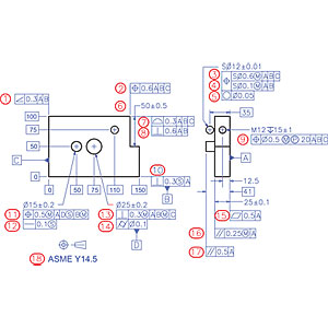
GD&T is difficult to get right even though it is very logical. What does “right” mean? Right means several things, but mainly that it imposes achievable, fully function based and only necessary permissible limits of imperfection using absolutely syntactically correct code. But right also means that controls are complete and logical. Many call-outs in the following drawing are syntactically correct but flawed in that they 1) fail to impose the necessary constraints, 2) utilize Datum Features in non-functional ways, or 3) misuse Geometry Control Tools and modifiers. Some are syntactically incorrect as well.
Take some time to study the call-outs below and make notes on each numbered item to log any problems you discover. Then put your notes away and only return to them for a second go at least one day later. When you feel you have a good handle on things, read through the numbered comments to compare your insights with ours. If you differ with our take, please email us your comments, and look for follow-up comments at www.qualitymag.com or in the forthcoming April issue. (This column will now appear quarterly.)
GD&T Code Commentary
- Legal and functionally correct. Although the Perpendicularity tool would state the requirement more clearly, the Angularity tool is perfectly legitimate, and properly implemented. In fact we don’t need the Parallelism and Perpendicularity tools in the first place, since the Angularity tool can do everything.
- Illegal on one count. The Position tool may only be used to constrain the location of the form perfect symmetry components of features—mid-points, axes and mid-planes—never of a planar surface. Note: This is not the case in the ISO 1101 Standard, which most “foolishly” and unnecessarily allows application of the Position tool to planar surfaces.
- Legal. The Position tolerance zone is spherical, and is correctly identified by the modifier “SØ”.
- Legal but functionally meaningless. The Datum Features in the second tier of a Composite Feature Control Frame may only constrain rotational degrees of freedom, but a stand-alone sphere has none! In the case of a pattern of two or more spheres, however, the second tier would impose refined mutual location constraints on them, and refined control over the orientation of the pattern.
- Illegal on two counts. The Circularity tool is the only permissible tool we have to impose Sphericity, even though the Y14.5 2009 Standard could be “interpreted” to permit using the Surface Profile tool to do so in conjunction with a toleranced nominal spherical diameter (see §8.4.2 p.165) but 1) the tolerance zone shape modifier “Ø” is inappropriate because the imposed tolerance zones are circular ribbon-like, and 2) the spherical diameter tolerance value of ±0.01 already imposes an upper limit on Sphericity of 0.02.
- Illegal on one count. The two indicated planar surfaces do not make up a feature of size—they are not opposed—making use of the width tool meaningless because it cannot define an envelope of perfect form at MMC and must by definition. The only two tools capable of imposing the indicated mutual location constraint are the Surface Profile and the Dimension Origin tools, both of which would also very appropriately differentiate between the controlled and the reference feature in order to encode the actual functional requirement, of which the width tool is also incapable.
- Illegal on one count. Surface Profile is the right tool; however, there should be no reference to Datum Feature C, since it has no influence on the Tolerance Zone.
- Illegal on two counts. 1) The indicated feature is nominally perpendicular to A but nominally parallel, not perpendicular, to B. The only functionally applicable tool is Angularity. 2) The Surface Profile tool has already imposed an orientation constraint of 0.3 millimeter (mm), making the addition of the Angularity tool meaningless without a tolerance smaller than 0.3.
- Non-functional on three counts. 1) The Tolerance Zone Size modifier (M) is totally non-functional in the case of a threaded feature which will always stably orient and locate the mating screw “regardless of its size” as soon as it is torqued down, and is even less representative of the functional impact of a threaded bore when accompanied by the Projection modifier (P), since there is no “material” surrounding its projected axis to create a functional Maximum Material Boundary. 2) Datum Features A and B suffice fully to define the necessary Datum Reference Frame in this case, making a reference to C inappropriate. 3) The intended offset of the Position tolerance zone from A is specified by a nominal dimension, which has no impact on a Position tolerance zone.
- Illegal on one count. The Tolerance Zone Size modifier (S) is illegal, because the controlled feature component is a surface, not a symmetry component.
- Illegal on two counts. 1) The lack of the Tolerance Zone Shape modifier “Ø” implies a “slab-like” tolerance zone, whose orientation has not been made clear, and even the proper definition of which would also leave the location of the feature uncontrolled in the orthogonal direction. 2) Although a Tolerance Zone Mobility modifier (S), (M) or (L) is required by default in the case of a location constrained planar Datum Feature, namely the implied relationship of Datum Feature B to D, B has not been controlled relative to D, making it impossible to define a Maximum Material Boundary for B relative to D, therefore outlawing the use of the modifier (M).
- Legal. Median Line Straightness can be controlled in the current instance. Furthermore the tolerance is smaller than the total tolerance on the size of the feature, therefore refining the constraint imposed by the Envelope Rule, is always associated with a Tolerance Zone Size modifier because the Median line is a symmetry component, and even allows an explicit (S), given that the date of the applicable Y14.5 Standard has not been specified.
- Illegal on three counts. 1) The Perpendicularity tool is unable to impose the necessary location constraints leaving the feature afloat in the imposed Datum Reference Frame. 2) The Tolerance Zone Shape modifier “Ø” is missing, which is required to fully constrain the feature’s bounded axis. 3) The Tolerance Zone Mobility modifier (M) associated with Datum Feature B is illegal, because B is a location unconstrained planar Datum Feature.
- Illegal on one count. The Cylindricity tool imposes a “tube-like” tolerance zone, not a cylindrical zone as falsely imposed by the Tolerance Zone Shape modifier “Ø”.
- Illegal on one count. The Flatness tool may never be associated with a Datum Feature label.
- Illegal on two counts. 1) The Tolerance Zone Size modifiers (S), (M) and (L) apply only when the controlled feature component is a symmetry component, namely a mid-point, an axis, a median line, a mid-plane or a median plane. In this case the controlled component is all the points on the surface of planar Datum Feature A. 2) The thickness control on the slab of ±0.1 already imposes a Parallelism tolerance of 0.2 on the indicated surface, making the additional Parallelism control useless.
- Non-functional on one count. The Parallelism tool defines a slab-like tolerance zone that can only be oriented by the implied Basic angle of 0 degrees, but not located by the applied Basic dimension of 41 mm, making it useless, therefore leaving the height of the pin uncontrolled.
- Illegal on one count: Failure to state the date of a particular version of the Y14.5 Standard makes all the indicated code meaningless from the get-go.
I’m certain that I will have overlooked or improperly analyzed several improprieties in the above drawing so I look forward to your comments.
Looking for a reprint of this article?
From high-res PDFs to custom plaques, order your copy today!


