GD&T Workshop
GD&T Best Practices
Controlling the geometry of slots.
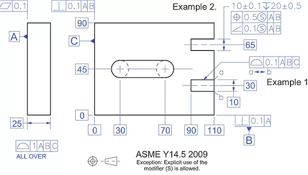
Image courtesy of Bill Tandler
Figure 1. Alternative Approaches to Controlling an “Open” Slot
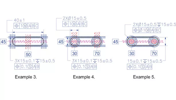
Image courtesy of Bill Tandler
Figure 2. The “Mid-Line,” the “Bi-Directional” and the “Double Ended” Approaches to Controlling a Round Ended Slot
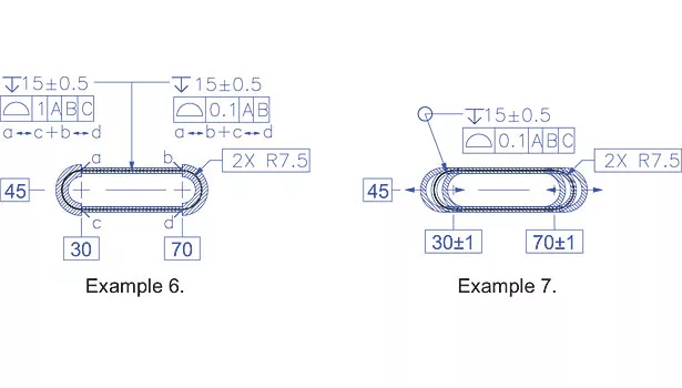
Image courtesy of Bill Tandler
Figure 3. The “Between” and the “ALL AROUND - Stretching” Approaches to Controlling a Round Ended Slot
Once we come up with a useful set of concepts (a Datum, Cylindricity, the Virtual Condition), it’s time to create a set of tools with which to implement them. And once we have a set of tools, we need a set of rules to make sure we don’t misuse them. Next it’s time to put them to work, and we do that with processes, like the feature function analysis process, the Feature Control Frame stuffing process, and the Feature Control Frame decoding process, etc. And once we’re into processes, we come face to face with the need for “best practices.”
Let’s look at what it takes to control the geometry of slots, and see if there is indeed a “best practice.” First of all, what is a slot? In fact an “official” slot consists of nothing but two opposed planar surfaces whose normal vectors point toward each other, end of story. The round ends of a slot, if it has them, or its bottom, if it has one, are not parts of the slot, but merely terminate it in various ways.
The Single Ended, Through Slot
Let’s start by focusing on the simpler of the two alternatives shown in Figure 1, namely the single ended through slots on the left hand edge of the part. The first question is always: “What are the functional objectives of the slot which we will need to encode?”, the second is “What can go wrong?” and the third is “What tools should we use to impose adequate, but fault tolerant controls?” In answer to question 1) let’s say the slot’s primary function is to very reliably orient a mating slab whose location and depth, however, are five times less important. In answer to question 2) there could be problems with the size of the slot, with the form of its surfaces, with its orientation, and finally, with its location and depth. Working toward an answer to question 3), the two most important requirements for meeting the most important objective, namely orientation, are first, that there be very little play between the slot and its mating slab, and second, that the slot’s perpendicularity to A and parallelism to B be tightly controlled. Let’s see how the two illustrated alternatives stack up:
Example 1—The “Everything” Tool: Because the Surface Profile tool can do “everything,” namely control size, form, orientation and location, and is very clean and simple to apply, it’s very attractive. In this case, with the help of the “between” modifier, Surface Profile creates three planar, skin-like tolerance zones which actually do control everything. They control the form of all three faces, the mutual offset and parallelism of the two opposing faces—and therefore the size of the slot—and also the orientation and location of all three faces relative to the Datum Reference Frame (DRF) defined by Datum Features A, B and C. That’s everything, so we are in fact done. However we also see that the “everything” tool has imposed a heavy hand, namely by using the same tool only once to control everything, we’ve had to impose unnecessarily tight tolerances on the location of the slot and on its bottom, in order to have the required tight tolerances on its size and orientation. As a result, by keeping things “simple,” we are pushing up manufacturing costs and increasing the chances that fully functional parts will have to be discarded. We therefore have to ask if there’s a way to separate control of the slot’s width and orientation from its location, and to treat its bottom entirely independently.
Example 2—The “Mixed Bag” Tool Set: Starting down a new path, if we use the good old fashioned “width” tool to control the size of the slot, then, as a result of the Envelope Rule and the Rule of Size & Form (Rule #1), we will also control its form, namely the flatness of both surfaces. Next, if we use the Position tool to control the orientation and location of the slot’s mid-plane quite loosely, and then the Angularity tool (neither the Perpendicularity nor the Parallelism tool are appropriate in this case) to refine control of its orientation, we will have imposed truly functional but also cleverly fault tolerant requirements on the slot. And, when it comes to controlling the location of the relatively unimportant bottom of the slot, the good old fashioned depth tool is just ideal, and we are done. Note: Because of the already present, very loose ALL OVER Surface Profile tolerance imposed on the entire part, instead of adding the depth tool, we could have left the bottom of the slot under its control. On the other hand, tying all the controls imposed on a single group of related features together, has lots of ergonomic benefits.
The Round Ended, Blind Slot
Moving on to the round ended slot, we again start by asking what are its functional objectives and what can go wrong, before we start to worry about selecting geometry control tools. In terms of the functional objectives, in general it is only the opposing faces of such a slot which are critical, making its ends merely convenient terminations whose main function is to stay out of the way. In the current case, let us propose that this time both the orientation and location of the slot are critical, and that it serves to reliably both orient and locate a mating slab. When it comes to determining what can go wrong, focusing on the opposed faces, we must control their mutual distance, their parallelism and their form, and in addition, their orientation and location relative to DRF[AB]—namely in this case Datum Feature C has no impact. When it comes to the round ends, we must control their diameter, their form and their orientation and location relative to DRF[A,B,C]—yes, now C does have an impact—but across the board much more loosely than in the case of the parallel faces.
Note: Because the process by which the round ends will be manufactured—a computer controlled end mill sliding back and forth—guarantees that they will probably be just as “perfect” as the opposed faces of the slot, loosening their tolerances will have little impact on reducing manufacturing cost. Nevertheless, to not loosen those tolerances might lead to the unnecessary rejection of perfectly functional parts, therefore making those looser tolerances a financial must.
Figures 2 and 3 show five different possible approaches to imposing controls, and in each case, all the tolerance zones as well, whereby those for size are shown in blue and those for orientation and location in red. The tool used to control the depth of the slot is the same in all five cases, namely the beautifully simple depth tool.
Example 3—The “Mid-Line” Approach: Here, the width and Position tools at the bottom of the illustration apply to all three features and serve to control 1) both the width of the slot and the “up/down size” of the rounded ends, 2) the orientation and location of the mid-plane of the slot, and 3) the up/down orientation and location of the axes of the rounded ends relative to DRF[A,B]. The width and Position tools at the top of the illustration, on the other hand, control the distance between the two line elements at opposite ends of the rounded slot, and the left and right orientation and location of the median line of those two line elements relative to DRF [A,B,C]. In this alternative, no direct controls are imposed on the form of the rounded ends which is comfortably left to chance based on the manufacturing process.
Note: In all three cases, the Tolerance Zone Size (Material Condition) modifier (S) is appropriate for the slot, because it “encodes” its “aiming” or “centering” function, whereas the modifier (M) is appropriate for the rounded ends to “encode” their “clearance” function.
Example 4—The “Bi-Directional” Approach: Here the controls at the bottom of the illustration are identical to those in Example 3, but those at the top now control the diameters and therefore the size and form of the two cylindrical ends, as well as the left/right orientations and locations of their axes rather than the symmetry element of their opposed surface lines, as was the case in alternative 3.
Example 5—The “Double Ended” Approach: Here the width and Position tools at the bottom of the illustration apply only to the slot and fully control its width and form as well as the up/down orientation and location of its mid-plane. The upper controls, for the first time, control all the characteristics of the two cylindrical ends independently of the slot, and in a fully functional, very fault tolerant way. Alternative 5 is by far the most attractive alternative so far.
Two More TAKES ON the Round Ended Slot
Having ignored the “everything” tool so far in the case of the round ended slot, because it dangerously usually controls “everything” to the same extent at the same time, it might be interesting to “play” with it anyway and see where it takes us.
Example 6—The “Between” Approach: A very simple way to control the geometry of a round ended slot would be with an All Around Surface Profile tool. But just as in Example 1 for the single ended through slot, we’d be imposing improperly tight tolerances on the round ends in order to fulfill the tight requirements on the walls. With the help of “Between” modifiers, however, we can apply the required tight tolerances to the opposed faces, and at the same time, the permissibly loose tolerances to the rounded ends in a most efficient and fault tolerant way. Pretty interesting!
Example 7—The “All Around - Stretching” Approach: How about another idea? How about trying the All Around Surface Profile tool this time, but allowing the 0.1 mm thick tube-like portions of the tolerance zone at the rounded ends to slide left and right using variable Basic dimensions? This is actually implied as permissible under the Y14.5 2009 Standard as shown in Fig. 8-27 (p.179), but where a variable nominal instead of a variable Basic dimension is used to permit a stack of straight ribbon-like, Line Profile tolerance zones to slide up and down! Our Example 7 is essentially identical and represents a very functional solution.
Because it is blatantly illogical to permit a toleranced nominal dimension which serves to control the size of a slab – see the Y14.5 example – to also control the location of a Profile tolerance zone, it seems time to get that corrected in the Standard and finally authorize the use of variable Basic dimensions.
And so, of all five alternatives for the round ended slot, which feels the best? I like alternatives 6 and 7 best myself, but because 7 is currently “illegal,” in the end, 6 seems the most fault tolerant as well as the most intuitive and simple approach.
Comments? I would appreciate complimentary as well as critical ones all the time, and also, topic ideas you’d like to see addressed that I might miss. In our July workshop, we’ll continue looking at best practices, so please stay tuned.
Looking for a reprint of this article?
From high-res PDFs to custom plaques, order your copy today!


