Ultrasonic Testing of Fiberglass and Carbon Fiber Composites
Ultrasonic testing provides a ready and well-established technique for locating and documenting internal flaws.
As the use of fiberglass and carbon fiber composites in manufacturing has grown, so has the need for reliable nondestructive testing, both in the initial fabrication stage and while in service. Traditional fiberglass is commonly used in tanks, pipes, boat hulls, wind power blades, structural panels, and similar products. Carbon fiber reinforced plastic (CFRP) has become steadily more important in the aerospace industry as an increasing number of military and civilian aircraft designs are based around the light weight and high strength properties of advanced composites. Because of their laminar layup structure, these materials are potentially subject to cracking parallel to the surface, either because of applied stresses or weaknesses resulting from manufacturing anomalies. These hidden internal cracks can have a significant impact on structural integrity and are normally not detectable by radiography or NDT techniques other than ultrasonics. Fortunately, ultrasonic testing provides a ready and well-established technique for locating and documenting internal flaws.
Ultrasonic flaw detection and thickness gaging are based on a simple principle of wave physics. A high frequency sound wave that has been generated by a small probe called a transducer and coupled into a solid medium like fiberglass or composites will travel in a straight line perpendicular to the surface until it encounters a material boundary such as a far wall, another material interface, or a lamination. At that point, the sound wave will be reflected in a predictable way. Thickness gages measure the round-trip transit time of the sound pulse and then use the programmed speed of sound in the test material to calculate thickness. Ultrasonic flaw detection analyzes echoes through a comparative process in which the echo pattern generated by a good part is compared with the echo pattern from a test piece. Since sound waves will reflect from voids or cracks, changes in the echo pattern indicate changes in the internal structure of a part. In testing fiberglass and composites, the instrument typically looks for the presence of echoes within a marked gate or window that represents the interior of the test piece. While the inhomogeneous nature of fiberglass and composites can generate scatter noise reflections even from solid material, cracks whose area approaches the diameter of the sound beam typically return strong localized indications that will be recognized by a trained operator.
The test frequency and probe size are selected based on the material being inspected and critical defect parameters. In general, higher frequencies and smaller beam diameters are required for resolution of smaller defects. Lower frequency probes are used to penetrate deeper into materials and offset scattering and attenuation of sound in materials with lower density or inhomogeneous structures. Probe selection and instrument setup should always be optimized for the job at hand.
Fiberglass parts and structures
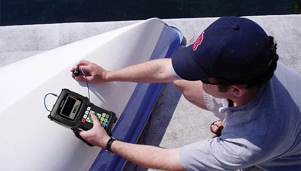
Fiberglass is most commonly tested with traditional ultrasonic thickness gages and flaw detectors using low frequency single element transducers, commonly at frequencies of 2.25 MHz and below, typically as low as 0.5 MHz when thicknesses exceed approximately 0.5 inch or 12.5 mm. Specialized low frequency transducers utilizing impedance-matching delay lines techniques can optimize both penetration and near surface resolution. Thickness gages designed to provide a direct readout of total material thickness are simple to use and require little operator adjustment following initial setup. Conventional flaw detectors display a pattern of sound reflections referred to as an A-scan, which will change as material conditions change and which is interpreted by a trained operator to identify anomalies. Ultrasonic thickness measurements are particularly useful with fiberglass mat/roving lay-ups where variations in layer thickness make it necessary to periodically check thickness during manufacturing, and crack detection is of particular importance in the marine surveying industry to check for possible hidden hull damage in older boats.
Carbon fiber composites
Just as contemporary carbon fiber composites represent advanced materials for manufacturing, they are commonly inspected by advanced ultrasonic instruments employing phased array imaging technology. While the size, shape and thickness of CFRP parts varies significantly, the nature of commonly occurring defects is ideally suited for compressional wave pulse echo ultrasonic inspection. Laminar defects caused by improper lay-up of materials or impact damage, unintended ply drops, and embedded structures largely occur in a plane normal to the surface, representing an optimum geometry for sound reflection.
Industrial phased array instruments are similar in concept and operation to medical diagnostic ultrasound scanners, but with probes and software optimized for engineering materials rather than human tissue. Phased array instruments utilize multi-element probes in which elements are individually pulsed according to a programmed sequence, creating the ability to steer beams and sweep them across an area of interest. Beam steering allows a single array transducer to generate an image across a sequence of angles (called a sector scan) or to produce an image from a fixed angle that travels over the length of a probe (called a linear scan). Additionally, beam parameters such as aperture (element group size) and focal distance can be controlled to provide flexible setups and superior results with a single probe. Typical linear array phased array probes for inspection of CFRP with thickness of 0.125 inch to one inch (3 mm to 25 mm) operate at 3.5 or 5MHz with 24 to 128 total individual elements.
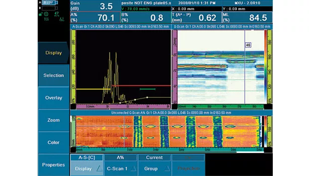
Signal amplitudes from a selected region of the test piece are plotted as associated color levels and as a function of position, creating a planar image referred to as a C-scan. This C-scan shows areas free of defects as represented by lower scale colors corresponding to minimal signal reflections, while higher signal reflections from defects are plotted to colors approaching maximum on the color scale. Defect sizing can be performed on this image data. In many cases the C-scan image will be produced by a mechanically encoded probe that tracks probe movement in the forward direction while the sound beam scans laterally, creating data on an x-y plot. This combination of electronic and mechanical scanning is often referred to as a one line scan. This simple scanning method is fast, fully portable and easy to implement with today’s portable phased array instruments. The footprint of the probe and encoder is quite small, so this method can be used accumulate swatches of data from a variety of part shapes.
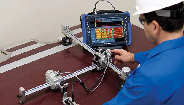
When inspecting large flat or near-flat CFRP panels, a two-axis mechanical scanner can be used. Some advanced instruments will automatically combine linear scans that are position encoded in two axes, dramatically increasing the speed of inspection as compared to conventional single element C-scanning. Scanner designs are lightweight, water resistant, and have mounting options to allow horizontal, vertical or upside down operation. With complete storage of inspection data, test results can be reviewed and analyzed after the inspection.
Inspection of radiused parts using conventional UT can be challenging because of coupling issues, but a linear curved array allows the acoustic beam to be stepped around either an ID or OD radius while maintaining normality to the part radius, producing live cross sectional visualization. The choice of the appropriate probe depends on the geometry of the part. The main factors that need to be considered are the inspection type (ID or OD), the radius of the corner, and the angle of the corner. Once the choice of probes has been narrowed, the thickness of the part as well as the footprint of the probe and wedge must be taken into consideration to ensure access to restricted areas that may exist. Probes are available to accommodate a variety of radii. Appropriate fixturing is required to enable and maintain alignment during scanning.
Conclusion
The ongoing development of portable ultrasonic technology has led to tools that offer new levels of reliability, efficiency, and documentation in nondestructive testing of fiberglass and composite. As with other areas of modern digital NDT, this evolution is likely to continue.
Looking for a reprint of this article?
From high-res PDFs to custom plaques, order your copy today!


