Computed Tomography Analysis Techniques
Industrial computed tomography cuts deep for applications beyond just porosity analysis.
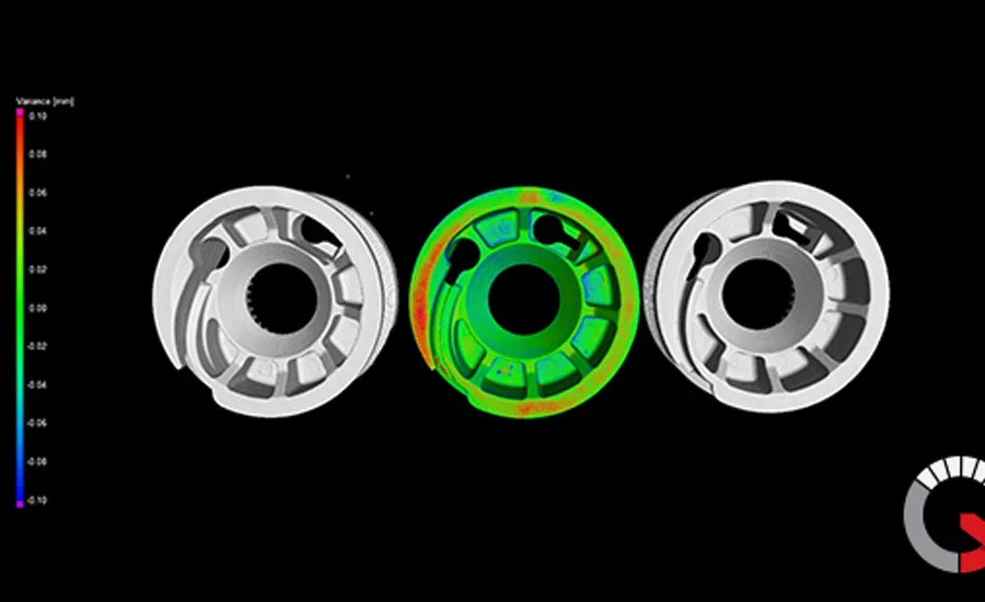
CT scanning software displays the analysis after scanning two parts and comparing both CT datasets to each other. Source: Jesse Garant Metrology Center
Industrial computed tomography has been a buzz-worthy technology for several years, and NDT experts know it’s a valuable tool for inspecting the complex internal geometries of 3D-printed parts, or for finding porosity in both additively and traditionally manufactured parts.
But the range of applications extends beyond the most well-known. Additional analysis techniques deserve a look, especially when, as Jesse Garant Metrology Center Technology Manager Andrew Good predicts, CT scanners become just as common in the lab as the ubiquitous CMM. That could be a likely scenario when “any of the big three, Ford, Chrysler, GM—or Boeing, GE, whoever—says we want our parts to be inspected using CT,” he says. “And then that will trickle down to all the producers of those parts.”
Broken down to its simplest description, an industrial computed tomography scanner consists of three elements: an X-ray source, a detector panel, and a rotary table. As the part spins on the table, the X-ray takes several hundred to several thousand projections, or images, which are then run through a reconstruction algorithm to create a 3D volumetric model consisting of billions of voxels. Each voxel is a cube with a discrete x-y-z position and density.
As mentioned, that 3D model can be inspected for a range of reasons, including porosity, voids, inclusions and other defects. Good walked Quality through porosity analysis, as well as several other analysis possibilities and applications supported by CT scanning software.
Porosity and Inclusion Analysis
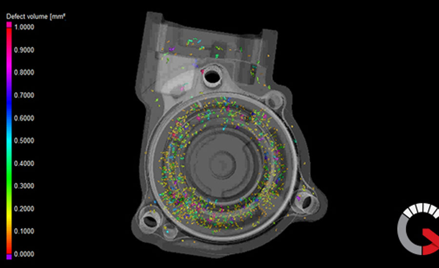
Viewing the part’s volumetric model on the computer workstation, each voxel is displayed in greyscale. Denser voxels appear lighter, and less-dense (or error) voxels appear darker.
“Think of it as when you’re looking at an X-ray image from the hospital, it’s usually in black and white,” Good says. “Your bones are bright white, and everything else is kind of black. Same sort of thing that applies for CT.”
Software creates a boundary around the part and around any internal porosity. Each pore can be identified by its x,y,z coordinate, as well as by volume size. The software can then provide percentages of porosity within selected areas, or of the entire scan.
Conversely, the software can draw boundaries around high-density areas to identify inclusions.
CMM Dimensional Measurement

Metrology-grade measurement functions are perhaps the fastest growing application with CT scanners.
“The process is very similar to a traditional CMM where you’re fitting lines, circles, cylinders, or planes to whatever you’re measuring,” Good explains. “So it’s basically the same principle, however the advantage of using the CT is it’s in a 3D space, where you can capture the internal as well as the external measurements, all in one shot. And the beauty of it is, once you’ve created a measurement template, any subsequent part that you scan of the same type, size and measurements, you can apply that measurement template to it almost instantaneously.
Imagine an aerospace part that has over 1,000 dimensions. “Once it’s been created and applied to the second one, instead of hours on the CMM machine and cutting them up, it can actually perform all of those measurements within 30 seconds,” he says.
The CMM capabilities of modern CT scanners can also perform part-to-CAD analysis.
“Where this actually becomes really important is lots of manufacturers are starting to move over into PMI CAD models,” says Good. “When they’re designing the actual CAD models, they’re embedding the measurement info. So when you import that into Volume Graphics, it’ll actually carry over that part measurement information to keep what the original engineer’s design intended.”
Wall Thickness Analysis
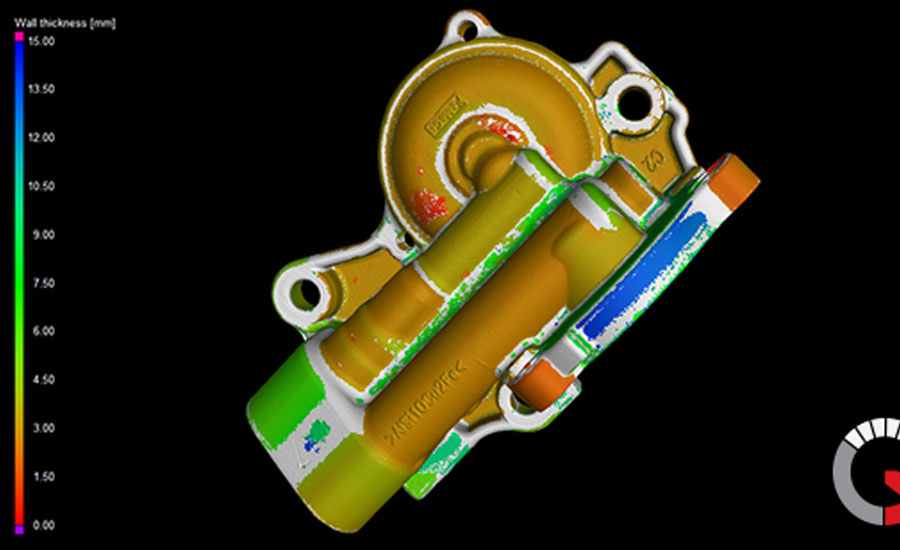
This function does what the name suggests. With CT, that means density information is provided along with the wall thickness of every wall in the part.
“In the past, you would have gotten in there trying to measure it, ‘Oh it looks good,’ but it wouldn’t have detected that porosity,” Good adds.
Fiber Composite Material Analysis
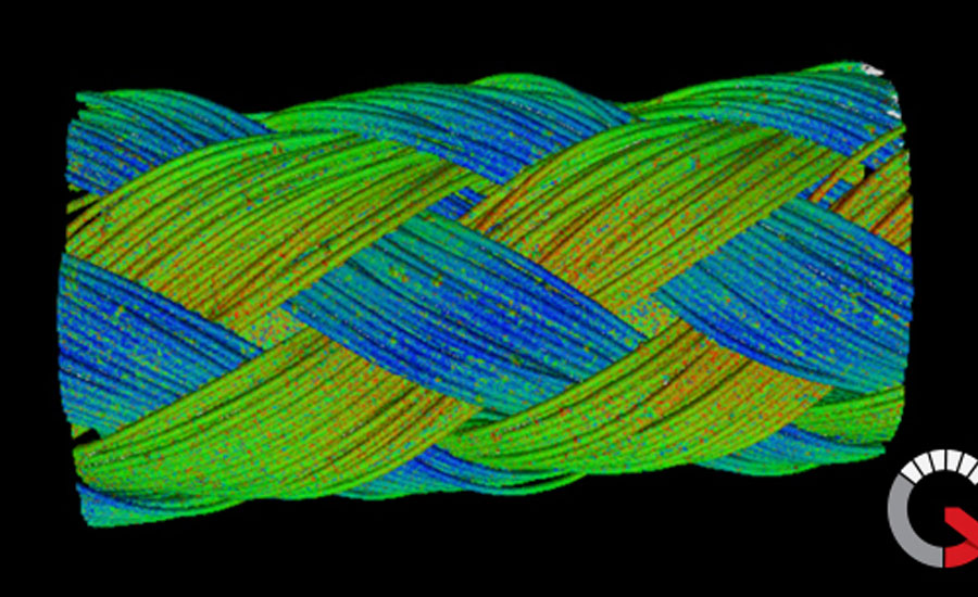
CT scanning can inspect a piece of fiber-reinforced plastic or other material, and analyze the direction and orientation of the embedded fiber.
“That’s really important for people who use integration meshes,” Good explains. “It basically makes sure that its fibers are flowing in a particular direction. It's kind of a nice analysis that’s not used by a lot of companies, but it is available.”
P201 Analysis
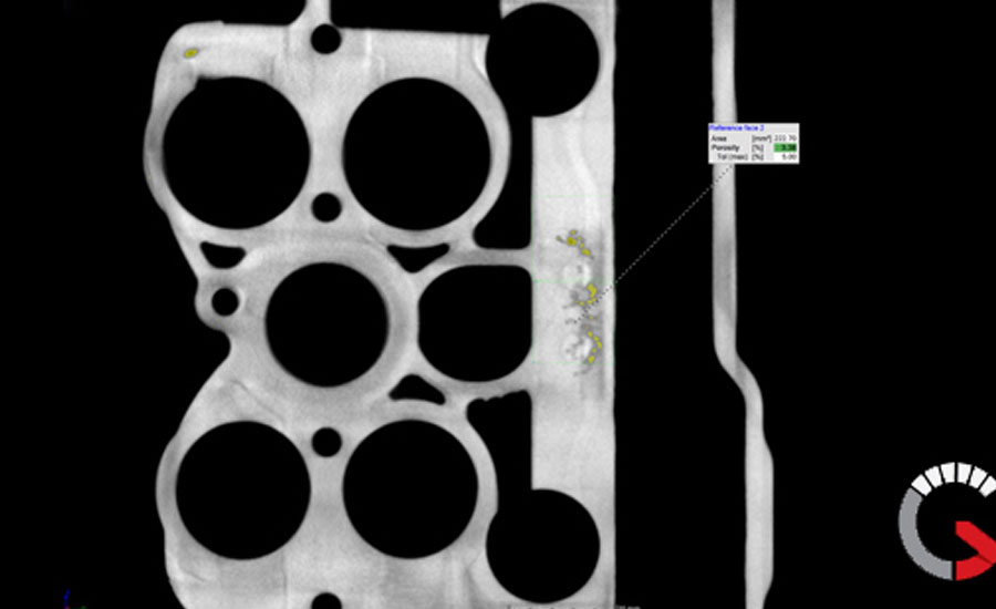
Volkswagen developed this technique for checking that each part doesn’t exceed maximum porosity percentages in key structural areas.
According to Good, the manufacturer supplies “call outs” with the maximum allowable pore size percentage at the critical locations. Those values are checked against the digital 3D cross-section of the part to provide a “go” or “no-go” answer.
Foam Structural Analysis
This application is especially well suited for medical implants that use a metal foam that’s designed to allow bone growth into the part, Good explains.
Looking Ahead
“CT, as a whole, can benefit every industry and can improve every aspect of our lives,” Good says. “Every product that we use, we’re always chasing to make faster, cheaper and better. And you know with CT you can do that. CT can give you the whole picture. Out of one part, you can perform seven different types of analysis, and get a good feel for the part that you’re actually making, rather than taking three or four parts and cutting them apart and measuring it and saying ‘That’s good.’
“Eventually it will get to a point where every high-value part might get CT scanned and fully qualified. Like, say, engine blocks or cylinder heads—if every engine block or every cylinder head gets CT scanned, then you can guarantee that you’re pumping out a quality product. It adds a layer of safety, because … you’re not relying off a random sampling. You can rest assured that what you’re getting is a quality product.”
Looking for a reprint of this article?
From high-res PDFs to custom plaques, order your copy today!


