Machine Vision Systems Integration
Techniques for putting the latest technologies and components to work in your applications.
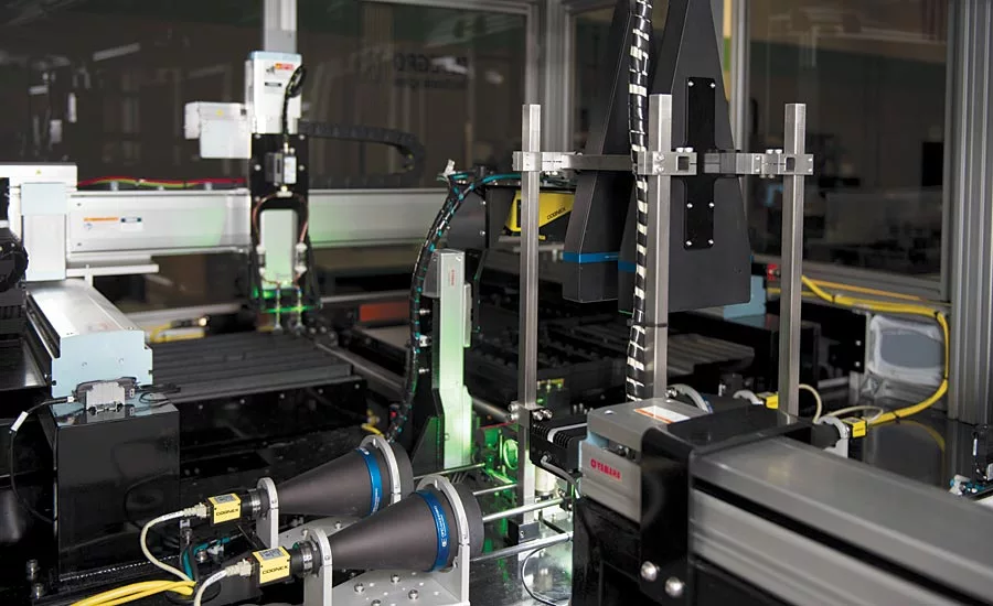
Demanding machine vision applications increasingly rely on the design, specification and integration of more complex components and systems for successful and reliable performance. Source: Integro Technologies
Recent record growth in the machine vision industry has been driven in part by continued advances in machine vision technology and components. The overall success of machine vision applications always has been indisputably tied to competent systems integration—the analysis, specification, design, and implementation of the components critical to the task. In this discussion, we will review machine vision systems integration and introduce some important technologies like 3D imaging, color imaging, deep learning and line scan imagers along with some practical information to help successfully incorporate and implement them in your inspection, metrology, and guidance applications.
Components that acquire and process a simple grayscale snapshot admittedly dominate the application base for machine vision in today’s marketplace. Certainly, these devices are very reliable, easy to use, and flexible for a wide variety of inspection, guidance, and metrology projects. However, there are other available technologies that could be better suited for certain applications and the only suitable solution for some. And in all cases, there are fundamental integration concepts that should be followed to ensure a well-designed and implemented machine vision solution.
With that in mind, let’s begin by briefly reviewing system integration best practices, and then discuss ways to apply and integrate some key machine vision technologies that go beyond the basic grayscale area camera.
Review of machine vision systems integration best practices
While critical to machine vision projects, these guidelines can be applied in any automation project in a variety of disciplines. Modify the fundamental concepts to best fit your needs.
Develop and use a formal application analysis document
Analyze and document the needs of the existing operation, process, or automation and gather all the details relevant to the targeted application, parts and products.
Document project specifications
Identify function and operations (inspections, guidance, measurements, etc.) that are to be executed by the system, as well as the related performance metrics. Detail the technologies that will enable the proposed system along with potential system limitations and exceptions.
Focus on “critical path” components
The machine vision system usually is the “critical path” component that, if it fails to perform as needed in the system might thwart the overall operation of the entire project. Design the system around the capabilities of the critical components.
Have an integration or project plan and organized task list
Use a project management software tool to keep the project on track but be sure to also address the details of the tasks, not just the timelines. Develop guidelines for implementing and configuring the machine vision, automation, user interface, and other components in the system. Test frequently.
Manage the project
No software tool can take the place of good project management, and technology projects do need management. Good communications between project team, sales, management and the customer can help ensure a successful application.
Installation – Refine, not design, online
While there are occasions where some imaging, process, or program development must be done after online installation, this should be the exception rather than the norm. The most efficient and successful projects are complete, tested, and validated prior to final installation.
Have and use a validation plan
Always have and use a written validation plan to quantify system performance. The document should outline the functional and operational criteria and metrics that indicate the system is working to specification.
Techniques for applying key machine vision technologies
There are more viable component choices than ever for the machine vision systems architect to consider and apply for successful integration of a wide variety of applications. Not all the technologies are new, but refinements in the devices and software are helping to make the components more broadly applicable and easier to integrate. Here we will describe just a few general technology categories that go beyond basic grayscale cameras along with some of the ways to incorporate them into a successful machine vision solution.
Line scan imaging
The term line scan refers to the fact that the imaging device is not taking a snapshot all at once (“area” imaging). The device captures only a thin “slice” or single “line” of image information and either processes that linear data (not common) or combines many lines into contiguous rows of a standard image for subsequent processing. One caveat that already might be clear; either the object or the camera must be moving to create the image.
Line scan imaging has many important benefits over area imaging in situations where it can be suitably integrated. Line scan cameras today feature sensors that range in width from about 0.5K pixels to over 16K pixels (the number of rows is variable depending on how many lines are selected for the resulting image). The resulting combined images can yield much higher resolution in terms of pixel count than would be available with area cameras, and potentially at a lower cost. Because line scan imaging only captures a single linear “slice” of the object at a time, the technique can produce very consistent images in some situations where an area camera cannot. Take the case of a cylindrical object (like for example, a beverage can or similar container). By imaging small slices of the circumference of the cylinder, a very spatially-accurate representation of the surface of the cylinder can be reproduced, something not possible with an area image due to the perspective of the curvature of the cylinder. In some implementations, line scan imaging can yield faster process times than imaging with an area camera. High speed line scan cameras can capture each line of the image at rates of over 120khz (frame rates vary based on camera and type of interface).
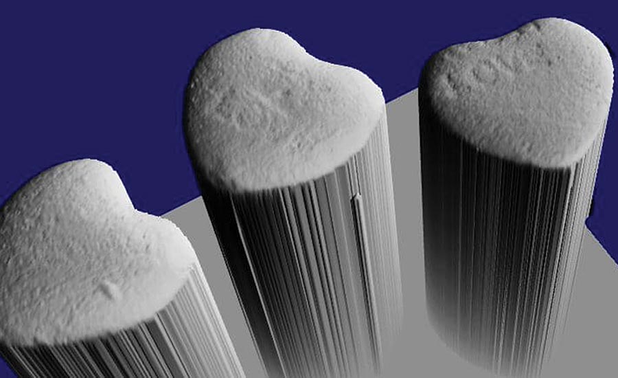
In many cases, 3D imaging provides useful data not available with standard 2D grayscale imaging techniques, including depth and profile information. Source: Integro Technologies
Illumination for line scan applications can be simpler than for area cameras considering that only a single line of pixels must be illuminated. Often a linear light source (either front lighting or back lighting) is all that’s needed to achieve a suitable image using a line scan camera. However, note that some of the lighting techniques that benefit area cameras might not always be achievable with line scanning.
Optics (lenses) for line scan application often present the greatest integration challenge. At a linear pixel width greater than 2K (depending on pixel size) usually a standard, familiar C-mount lens cannot be used with the camera, and a F-mount or even a more specialized lens must be specified. In some cases, the lens assembly for a line scan camera can be very large and require specialized mounting.
Integrating a line scan camera usually requires the use of an encoder to trigger the lines at proper spatial intervals. Configuration of the exact pulse timing relative to movement is dependent upon metrics like pixel spatial resolution, speed of motion, and frame rates. Fortunately advances in cameras and camera software are helping to make the configuration more user friendly.
3D Imaging
Many applications can benefit from the recognition or representation of objects and features as they appear in 3D space. In the past several years there has been notable growth in the availability and variety of 3D imaging systems for key machine vision applications like inspection, defect analysis, metrology, and robotic guidance. In fact, certain applications that simply cannot be reliably addressed with grayscale imaging are being successfully implemented using 3D technologies.
The key value in 3D imaging is that all the image information represents actual points in space instead of grayscale or color intensity values as with 2D imaging. These points may be calibrated to some known world coordinate system (especially when the information is used in guidance, for example), or simply analyzed relative to each other to extract features, defects, and perform 3D measurements. Note that a 3D system provides a “profile” of the surface as viewed by the camera.
In describing how to select components it can help to consider 3D technology in application categories.
Metrology and defect detection
Many 3D imaging systems targeted for metrology and defect detection compose an image using scanning and laser triangulation (sometimes called a distance or depth sensor). These systems can provide higher accuracies than other 3D imaging techniques, though these components have somewhat limited fields of view, and do require that the sensor or the part be in motion to capture an image. The imaging tools and algorithms commonly offered are designed to evaluate 3D features, and provide measurements including depth and sometimes position.
Guidance and object location or recognition
Other 3D systems focus mainly on applications for guidance, location and/or recognition. Some components in this category also use 3D laser scanning, while others use a variety of techniques involving structured lighting to gather the 3D points. With the latter, an advantage is that the imager takes a single snapshot without the camera or part being in motion. The image returned by these systems can be a depth image like a distance sensor as well as a collection also of 3D mapped points called a “point cloud.” Software in these systems targets guidance and location tasks in a variety of ways by combining neighboring points and extracting geometric features. These features might be simple location points, or even a 3D spatial matching of an object defined with CAD data. In implementation, the systems often can locate randomly oriented known and unmixed parts with good reliability, however recognition and location of random mixed parts or objects is an extremely difficult task which remains, for many applications, a research effort.
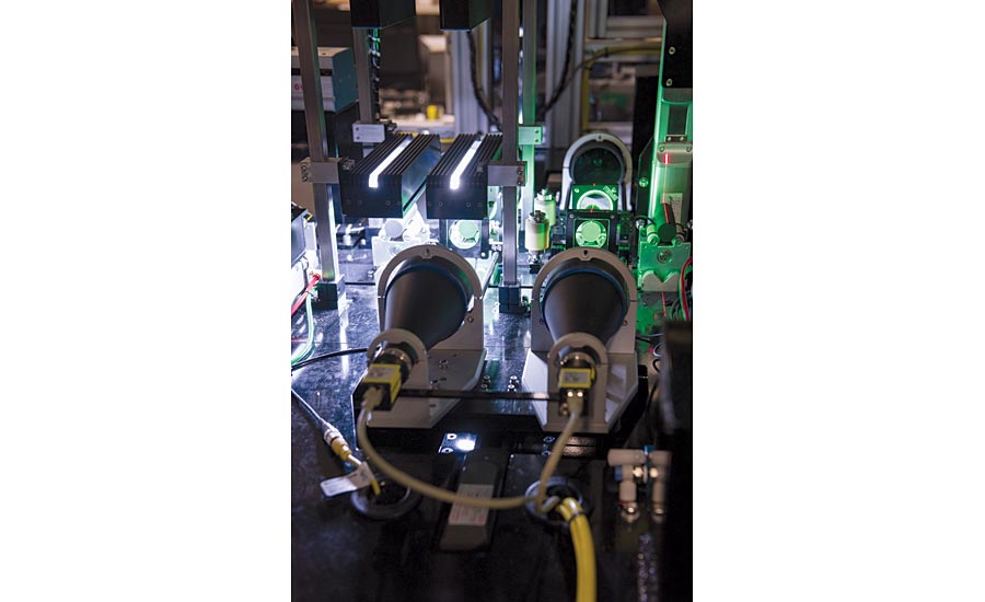
Source: Integro Technologies
CAD reconstruction
Some 3D imaging systems are designed specifically to scan objects and capture surface data for the purpose of transforming that data into a 3D CAD model for further processing. These are highly specialized systems which perform the reconstruction task well but cannot be considered for other tasks.
Deep Learning
Perhaps the hottest buzzword in the machine vision industry now is “deep learning.” Machine learning implemented with a software algorithmic method called “neural nets” has been around for many years. Deep learning is a recent extension of that technology specifically incorporating layers of networks called convolutional neural nets or CNNs. A simple description of the technology is that it classifies images, learning those classifications by example. (Think Google’s image search capability; you can upload a photo of a cat, and the “artificial intelligence” will classify it as a cat, and possibly even know the breed.)
Understanding neural networks and deep learning at its most basic levels is within the reach of most computer programming hobbyists. However, understanding the workings of deep learning is not necessary for the machine vision integrator seeking to implement the technology using the growing set of products and libraries that provide machine vision deep learning capabilities. Integration of deep learning machine vision is almost just a “show and go” process.
As good as that sounds, deep learning just isn’t well suited for all applications. Furthermore, there are key details in the integration that remain purely an imaging task. Applications where deep learning is very useful are those where subjective categorization is required, for example detecting non-conforming parts where the defects or non-conforming features are somewhat subjective, and the nominal good parts can be well defined (even if the good parts have some inherent variation). Where deep learning is not usually well indicated are applications where discrete analysis, metrology or location is required. There are applications which could be addressed competently by either standard machine vision, 3D imaging, color imaging, or deep learning and in those cases, one must weigh the integration and configuration costs and techniques.
A mistake made by many considering deep learning is to think that the technology automatically overcomes integration considerations like lighting, part presentation, and optics. In this sense, imaging for deep learning is the same as all machine vision applications: the objects, defects, or other features of interest must be differentiable from the rest of the part in terms of contrast and sufficient pixel resolution, and presentation must be controlled to ensure proper imaging.
Color, Multi- and Hyper-spectral imaging
The integration of color imaging for machine vision is invaluable for applications that need to identify, differentiate, or verify an object’s or feature’s color. Having color image data can enhance feature contrast and isolate features in some circumstances where grayscale images cannot. Standard color cameras and tools are widely available in basic machine vision systems and is an imaging option that can be easily considered and integrated where appropriate. The most common color cameras take images in three broad bandwidth color planes; red, green, and blue, and combine those color planes to create a full color image.
A more powerful color imaging technique which is not new but has become more widely available in recent years is hyperspectral imaging. This type of camera acquires images over many (sometimes 100 or more) very narrow color bandwidths often ranging from ultraviolet to near- or short wave-infrared. This enhanced capability allows the integrator to define complex color “profiles” for objects or features with an accuracy not available in basic RGB color imaging. Features, defects, and colors that might not be differentiable or visible even to the human eye sometimes are detected easily with hyperspectral imaging. Closely related to hyperspectral imaging is multispectral imaging. Multispectral cameras provide fewer color planes (usually less than 10) in the image and often the color bandwidths are selected and tuned to a particular application. Specification and integration of hyper- and multispectral cameras can be complex. Most hyperspectral systems must have the object(s). Selecting bandwidths and tuning the color profiles can require some specialized expertise in the technology.
In all color applications, a key integration challenge is illumination. Color content cannot be imaged without a light source that provides illumination over all colors of interest. The first instinct is to use a “white” light, but how do we define “white”? Unfortunately, popular machine vision light sources (like LEDs) may not be “white” in the sense that the source cannot provide uniform illumination without dropouts or strong peaks at some wavelengths. It’s possible that the “white” that is available is sufficient for a given application, just be aware that applications that require closer color differentiation usually require a more uniform white light source. Often the solution is to use an incandescent source like halogen or xenon, but new LED technology called “multispectral illumination” is recently available that comes closer to full bandwidth illumination by combining multiple LED colors and balancing the output.
In conclusion, standard machine vision components and systems remain an excellent integration choice, but having a broader toolset can enhance the scope of machine vision applications that can be successfully and reliably integrated. V&S
Looking for a reprint of this article?
From high-res PDFs to custom plaques, order your copy today!


