Custom Gages: You’ve made it, but can you inspect it?
Sometimes the only inspection solution is a custom gage.
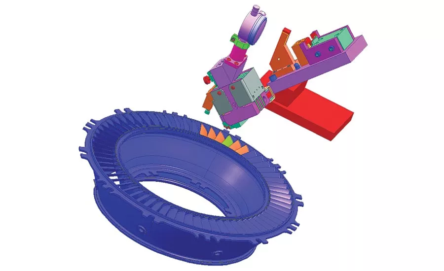
Custom vane gage shown on CAD drawing designed by Starrett Special Gage. Source: The L.S. Starrett Co.
From calipers to micrometers, to indicators and all manner of gages and metrology equipment, there are literally hundreds of standard off the shelf solutions for measuring the vast array of parts that manufacturers make. And with the often-assumed mantra of “if it can be made, it can be measured,” why would any manufacturing entity or inspection department be concerned about measuring a part, regardless of its complexity? Well, in metrology, as in life, there are a healthy number of exceptions to the rules.
Consider an exotic aerospace defense part with a labyrinth of grooves, vanes, holes, slots, shoulders, lands—a non-standard part worth well into five figures per unit. After designing and manufacturing the part, the manufacturer realized there was no way it could accurately measure the part. Pressed to deliver the part, the manufacturer sought a solution for the quandary and consulted our special gage division. After quick and intense analysis, a solution was drawn up, approved, and a custom designed and built gage was provided that ultimately solved their problem.
Going Custom: How and When to Decide
By examining a new product manufacturing program in depth well upstream during the design process, part feature inspection problems can easily be avoided. When a manufacturer launches a new program to make a complex or non-conventional part, among the key things it needs to determine besides how many parts can be made, the cost per part and how fast it can make them is how will the part be inspected and how long will the inspection process take?
It is not unusual for a company to design and make parts, only to discover that the parts cannot be properly inspected or the company has assembled a crude or rudimentary gage to attempt measurement. However, bringing custom gaging professionals into a program at the design stage or even before production ramps up is critical. Supplying prints and prototypes of the product is also very helpful, as well as knowing what the project timeline is and a budget range for the special gage solution. Both of these factors are also important, in addition to keeping an open mind on the solution. At times, a manufacturer may have a preconceived notion that a special gage will take “X” amount of time to design and build and cost “Y” amount of money, only to learn that the actual gaging solution was simpler, faster and under budget. In other scenarios, designing a more engineered solution for a complex application could take two to three months or more and require a significant investment. Whatever the situation, having advance notice and involving experienced gaging engineers early on in the process is vital to a successful program.
Specifying: Best Practices and the Process
Having an upfront dialog on the application details will set realistic expectations for the project. However even initial notice alone will not address all potential issues. Consider this real life example where custom gaging engineers have only been provided partial information about a job that outlined the part design details, as well as budget and deadline requirements. The special gage was created and approved for delivery by the customer. However, once in-house and ready to be used, the gage did not perform as intended due an interfering fixture that prevented the gage from reaching the part. No information had been provided about the fixturing setup. The gage had to be modified to the required diameter and drop criteria, which resulted in added time and cost. This actual instance could have been avoided if all information, including the fixturing details, had been initially communicated.
To facilitate a comprehensive, open dialog it is also important to note that if a project is of a confidential nature, the special gage supplier should be willing to sign a non-disclosure agreement.
Here are the general steps to expect during the special gage design and build process:
- Step 1: Consultation, Quotation, Acceptance & Specification
- Step 2: Design
- Step 3: Prototype (optional as required)
- Step 4: Test & Final Specification
- Step 5: Custom Gage Solution
Letting your imagination run wild, here are but a few of the ways that special gaging can solve inspection challenges.
Custom Caliper
Recently, a manufacturer sketched their own rough design of a desired gage solution so that our special gaging group could create a more streamlined version. We designed a few different preliminary prototype versions and brought these to our customer. On site, additional challenges revealed safety concerns and size restrictions. After this initial review, we provided a full prototype for customer testing, a process which took about a month. Once the company approved the prototype with a few required changes, we initiated manufacturing.
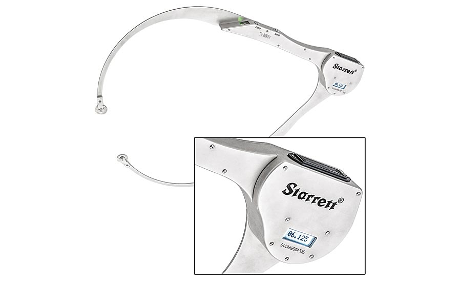
This is a digital electronic custom caliper. Source: The L.S. Starrett Co.
This efficient process resulted in custom manufacturing a wireless caliper that measures from 0 to 48 inches with an accuracy of .010 inch. Designed for a foundry, the caliper was made to be rugged but nimble, so that it could be used on materials up to 1,500 degrees F. When using the caliper, the operator measures 1,200 degrees F titanium forgings.
The gage is easier to maneuver than a normal caliper or gage of its size. This caliper is well-balanced, with the center of gravity meant to be in the user’s hands so that there are no issues with the user interface. A Bluetooth device is used to send data to the company’s in-house SPC software to ensure a safer, cordless application. We collaborated with our customer to write software to expedite the data transfer.
Aerospace Area Flow Gage
Custom designed for each application with generally moderate modifications, area flow gages measure the minimum area openings of turbine engine nozzles. Area readings are in .001 square inch resolution. The area flow gage uses eight or more contacts that reach into the throat of the turbine nozzle openings. The recorded measurements are transferred via hydraulic cylinders to a dial indicator.
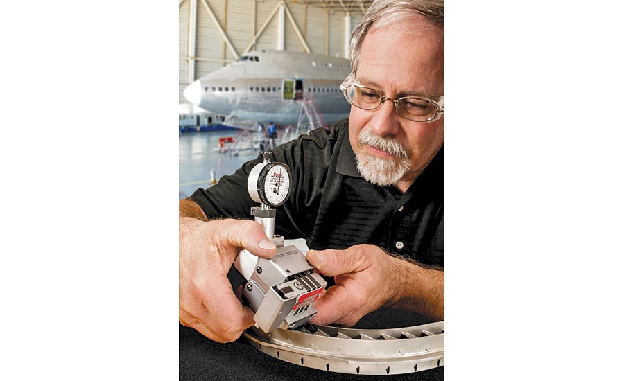
Area flow gages measure the minimum area openings of turbine engine nozzles. Source: The L.S. Starrett Co.
Using mechanical linkage and hydraulics, the algebraic area is transferred to the indicator or electronic probe at the top of the gage.
Openings of segments are matched and located opposite one another on the engine circumference to provide a balanced air flow. Gages are custom designed for each stage of the turbine. This gaging is critical to proper engine performance and operation.
Measuring Hot Steel During Heat Treating/ Forging
In another example, a new gage for measuring hot steel flat stock during the heat treatment process was needed. The old measuring device utilized a gage with a crude fractional dial that did not provide accurate or repeatable results. In addition, it often stuck to the hot steel and ruined the piece being measured. Even worse, on several occasions, the old process caused burn injuries to the operator.
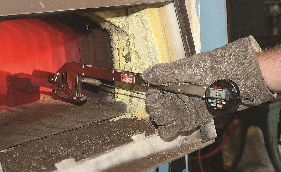
The new custom hot steel gage takes measurements quickly, with only two seconds of contact. Source: The L.S. Starrett Co.
After collaboration between the customer’s engineers and our special gage group, a radically different gage was developed that met all of the design criteria. The new hot steel gage takes measurements quickly, with only two seconds of contact. It uses an electronic indicator with a hold feature to lock the reading so it can be safely read away from the dangerous area, and in better light conditions. The custom hot steel gage is nickel plated to minimize radiant heat transfer. The operator’s hand now stays 12 inches away from the hot steel, and the gage is very accurate, measuring to ±.003 inch. Q
Looking for a reprint of this article?
From high-res PDFs to custom plaques, order your copy today!


