Computed Tomography for Nondestructive Testing
Analysis and visualization software is key to final quality.
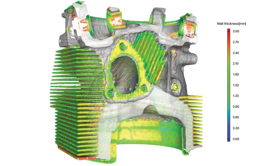
Image 1. A wall thickness module in CT-data analysis and visualization software automatically localizes and color-codes areas with an insufficient or excessive thickness or gap width directly within a voxel, point cloud, mesh or CAD data set. In this example, the module was used to examine the wall thickness of a Lycoming IO-540-E1B5 aircraft engine. Scan courtesy of YXLON US; image courtesy of Volume Graphics.
Coordinate measuring machines (CMMs), vision systems, the trusty micrometer—no manufacturer would argue the importance of traditional dimensional metrology equipment, but the fact remains that the tried and true sometimes comes up lacking. What happens when you can’t see or reach interior features? Is there any porosity or stress cracking deep within the workpiece? How about fiber orientation? And once a product has been assembled, how does one go about measuring the clearance between its mating components, the fit and function of the unseen interior?
Breaking the status quo
These are just a few of the instances where a more robust metrology approach is required. Yes, nondestructive testing (NDT) methods like magnetic particle inspection and eddy current are great for finding shallow defects, but that’s about all. Destructive testing is also a possibility, but the slice and dice approach is both time-consuming and quite expensive; worse, the cross-section taken from one area of a workpiece might suggest that all is well, while the view from an adjacent section could show something completely different.
Fortunately, there is an alternative. It falls under the umbrella of NDT, but is far more capable, often able to reveal extensive details of a part’s interior and do so rapidly. It’s called industrial computed tomography (CT), a technology quite similar to that used in hospitals and universities to image human beings.
Like its medical counterpart, industrial CT scanning uses a series of X-ray images to construct dimensionally-accurate images. The difference, however, is that industrial CT can see through plastic, metal, and more. It’s able to generate three-dimensional models of everything from engine blocks to integrated circuit boards. Further, when married to smart, highly integrated software, CT scan data can be put to work within a host of analytical functions, making it as much an engineering tool as a comprehensive metrology solution.
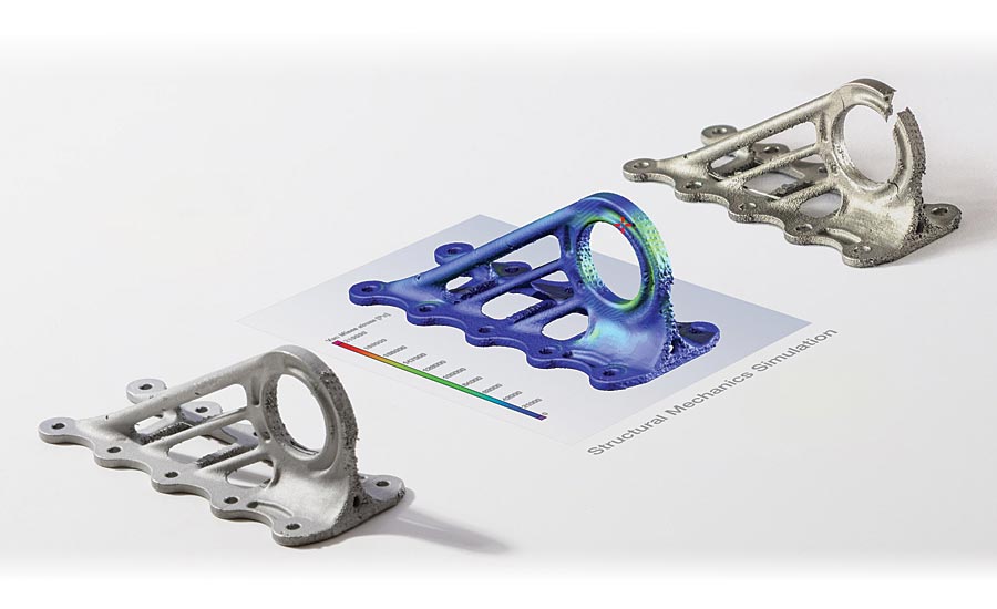
Image 2. (Left) An additively manufactured aircraft cabin bracket (miniaturized, without surface finishing, and with the typical appearance of a 3D-printed part) with deliberately inserted discontinuities. (Middle) CT-data analysis and visualization software generates a color-coded display of the locations of the weak points directly on the scan of the real component. (Right) Part after destructive test shows component failure in the exact spot predicted by the software. Part courtesy of Airbus Emerging Technologies & Concepts; software images courtesy of Volume Graphics; part manufactured by Concept Laser.
Who’s using it?
Industrial CT scanning is not new. It wasn’t long after the first computer-generated images of the human brain appeared in the early ‘70s that people began using CT-scanning to inspect manufactured components. The technology has since become an important tool for anyone who needs to understand everything about a product’s interior and exterior. A well-known automobile manufacturer, for instance, uses gantry-based high-speed CT scanners to measure engine-wall thicknesses and check for porosity in cast cylinder heads. Plastic injection molders validate their tooling by CT-scanning the parts coming out of those tools and comparing the results to 3D CAD models. The aerospace and defense industries inspect critical flight components with CT scanners, while composite manufacturers use CT scans to analyze fiber orientation. Museums even use the technology to detect fake artwork and sculptures. Industrial CT scanning is everywhere.
The reasons are simple. For starters, it’s a mature technology, making it both reliable and well-understood. Manufacturers and metrologists alike trust industrial CT scanning. And aside from its ability to see features and internal structures that traditional metrology methods can’t, the scanning process itself is much faster than the multiple inspection steps that would otherwise be required, especially where destructive cross-sectioning is involved. In many cases, a workpiece can be placed into a CT scanner, imaged, and validated inside and out within minutes. The result? Lower inspection costs, higher throughput and, often, greater ease-of-use.
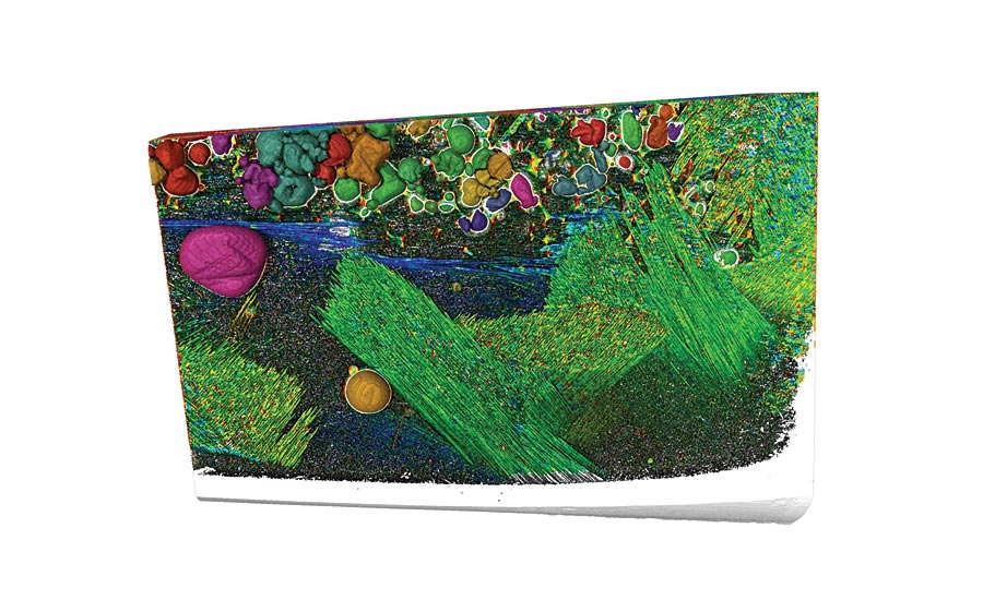
Image 3. CT-data analysis software clearly shows the fiber orientation within a helicopter rotor blade made of lightweight, fiber-reinforced plastic composites (GRP). Scanning courtesy of TPW Prüfzentrum, image courtesy of Volume Graphics.
Detecting defects
Beyond efficiency comes enhanced value of data. Where CMMs and vision machines generate only dimensional data, CT scanning—when used with the right software—provides previously unavailable information on, and deep analysis of, internal structures, material properties, potential failure points, and more.
Consider porosity, a defect that often goes undetected with conventional inspection methods. CT-data analysis and visualization software is used for a wide variety of defect analyses, especially when combined with associated porosity and inclusion add-on modules. This digital tool, developed in collaboration with leading foundries, is suitable for hundreds of applications. One industry-specific challenge, for example, occurs when the individual pores within a casting are situated at the resolution limit of the scanning device, and intelligent image processing is needed to reliably identify defects. This is precisely what the defect-analysis function within the software does. Further, this utility doesn’t stop at recognizing defects but also delivers information as to why the component is good or bad—by evaluating the size and shape of the pores relative to their position in the component’s wall, for instance.
Also available are fiber analyses, which might be used by an aircraft manufacturer to validate the integrity of a carbon-fiber layup, and foam-structure analyses, which are important to furniture producers, automakers, and commercial-goods manufacturers. Similar capabilities exist for plastic injection-molded parts, forgings, machined- and sheet-metal components, and parts produced via additive manufacturing (AM or 3D printing). Simply put, if there’s something not quite right about a product, it’s possible that there is a software analysis mode that will not only find it but help you to fix it as well.
Geometry considerations
CT-data analysis and visualization software goes beyond finding mechanical defects to provide a wide array of geometric analysis and metrology tools. In addition to the aforementioned measurement of wall thicknesses, there are nominal-to-actual comparisons, reverse engineering capabilities, and the digital imaging of part features and surfaces that would otherwise be impossible to recreate.
Returning to the injection molding example, in a traditional manufacturing environment, the toolmaker would receive the inspection results from the initial pre-production run and be left to correct the mold cavities based on his or her experience and skill level. However, by clearly identifying any deviations from the nominal, the software can actually help guide tool geometry recommendations, quantifying the subjective and streamlining what can be a painstaking process. Similar correction data is available for casting and forging processes, sheet-metal forming, composites and 3D-printed parts.
There’s also structural-mechanics simulation, which includes the ability to evaluate stress distribution under external loading, even while factoring in overall porosity and other defects. The results can be compared to simulations run against a part’s CAD model and displayed both visually and numerically. The software works directly on scanned surfaces and internal voxels, eliminating any pre-processing mesh conversion. This makes it faster and easier to run simulations against CT-scanned data—and more accurate as well. Automakers and aerospace manufacturers use the software to ensure they’re producing strong but lightweight parts, moldmakers use it to make better molds, additive manufacturers use it to optimize their builds and part designs. The list goes on.
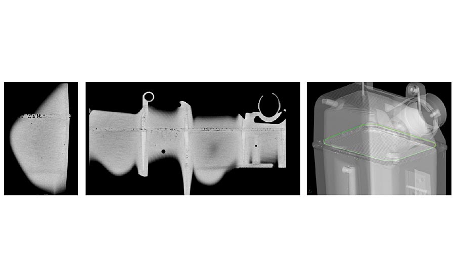
Image 4. (Left): Regular orthogonal CT slice of a weld seam; only a small portion of the existing pores are visible. (Middle): CT-data analysis and visualization software provides an “unrolled” view of the same weld seam; pores and cracks are clearly visible along the entire weld seam. (Right): 3D rendering of the tank showing the path (green) used to unroll the weld seam. Images courtesy of Volume Graphics.
Machine and data connectivity
CT-data analysis and visualization software can be applied to a broad portfolio of industries and processes—which brings up the topic of interoperability. After all, there are dozens of CT scanning equipment brands and service providers and a variety of CAD tools and metrology packages. How do you know what works with what? How can you ensure that CT scanning will coexist and interact with the rest of your manufacturing processes?
With a more extensive, independent, software-installation base, and a significant market share, the portfolio of my company’s CT-data analysis and visualization software products is recognized for universal applicability and can be used anywhere that industrial CT scanning is involved.
Advanced CT-data analysis and visualization software has led the way with groundbreaking innovations, expanding the use and capabilities of what many feel is one of the most important manufacturing and metrology developments of the past century. Additional interfaces to other software tools are under development and CT scanning software is now embedded into customers’ diverse workflows, simplifying what would be a cumbersome process and continuing a deep collaboration between R&D and real-world user applications. At the same time, close collaboration is ongoing with hardware manufacturers to address their needs and ever-expanding capabilities, thus ensuring that the software-side of the equation remains the core component of the CT scanning industry overall.
Looking for a reprint of this article?
From high-res PDFs to custom plaques, order your copy today!


