NDT | X-ray CT
High Speed X-ray Computed Tomography for Quality Control
Advances in X-ray computed tomography enable rapid nondestructive, 3-dimensional inspection of die casted and molded parts.

Image Source: Getty Images
This article provides a quick review of X-ray CT system design and shows how rapid X-ray CT scanning can be a powerful production quality control tool to nondestructively image internal voids, inclusions, and other defects in molded and die-casted products.
Background
X-ray computed tomography, or X-ray CT scanning, is a powerful nondestructive imaging technique with widespread industrial applications. The technique enables detailed three-dimensional imaging of the internal structure of materials without disassembly. It can be especially useful as a quality control tool to support the manufacture of items where internal defects such as voids and inclusions can significantly degrade product quality. Common applications include the inspection of aluminum diecast and molded plastic parts for unintended voids, the inspection of electronic components for internal disconnects, and the inspection of consumer product and food packaging for defects and foreign matter.
This article provides a basic review of the X-ray CT technique and describes a recent tabletop system design that greatly simplifies the acquisition of detailed CT images. Complete CT scans can now be acquired in as little as 12 seconds by non-expert operators using a compact tabletop system.
X-ray Computed Tomography Technique Basics
The primary components of an X-ray CT scanner are an X-ray source, a precision rotary stage, an X-ray detector, and a control computer with data acquisition and analysis software. A generic schematic of the main components of a CT scanner is shown in Figure 1.

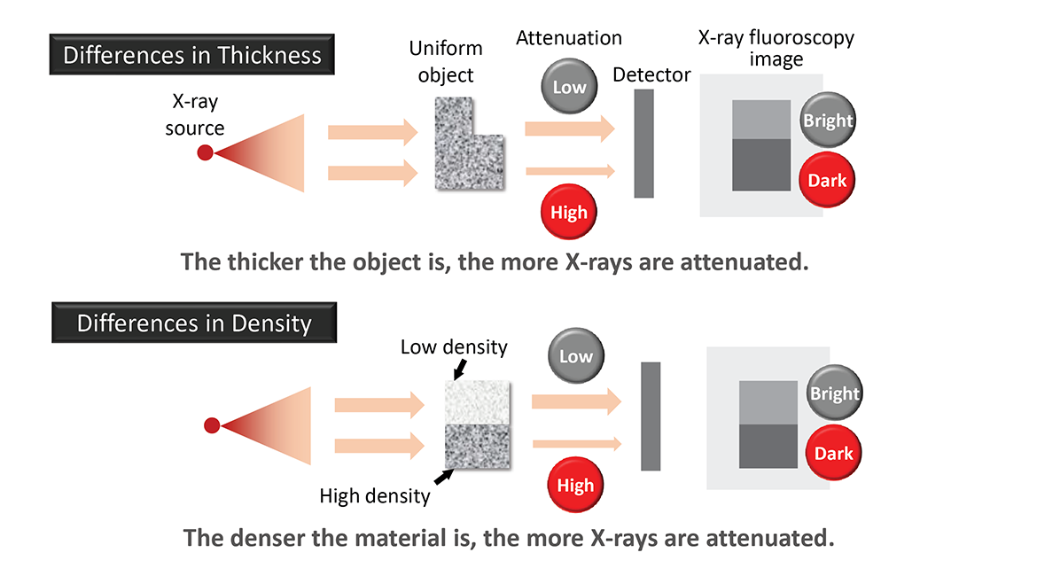
To create an X-ray CT scan, a test object is placed on a precision rotary stage. An incident X-ray beam is transmitted through the object. The incident X-ray beam is attenuated by variations in the object density and thickness (figure 2). The X-rays that pass through the object enter a detector, and a two-dimensional “fluoroscopic” image is projected and stored. The object is then rotated a small step, and another projection is obtained and stored. This sequence of rotation, image acquisition, and storage is continued until the object has been rotated 360 degrees. The number of projections acquired depends on the step size of the angular rotation between each acquisition step.
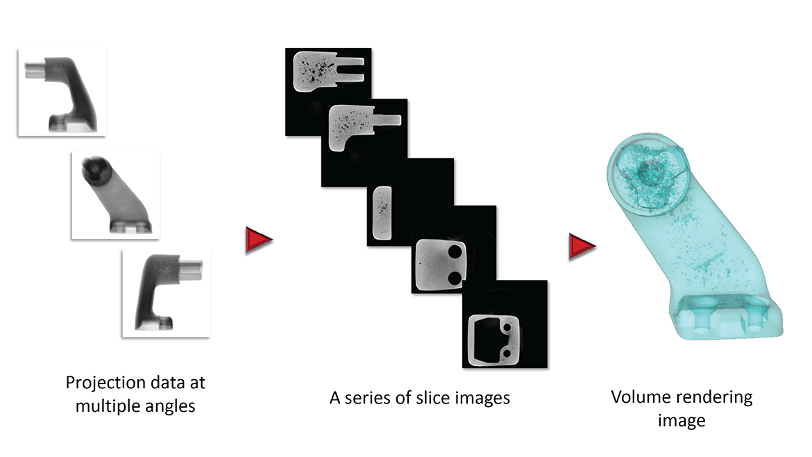
The collected projection data can then be mathematically processed to generate a sequential array of slice images which enable viewing and analysis of separate user-defined planes within the scanned object. The collected image slices may also be displayed in three-dimensional Volume Rendering (VR) mode, which can used to analyze internal information such as porosity and the location and size of voids and inclusions.
Figure 3 shows an example of images taken of an aluminum die-cast part during each phase of the analysis.
The characteristics of the aforementioned components determine the overall performance of CT scanning system designs. For example, the maximum energy of the primary X-ray beam (measured in kV) imposes density and thickness limitations on the types of samples that may be imaged effectively. The detector size limits the effective sample volume that may be imaged, while the number of detector pixels influences image resolution and quality. The weight-bearing capacity and precision of the rotary stage define the maximum dimensions and weight of the test object. The scan geometry, the data acquisition devices, and analysis software influence the speed of analysis and data output.
Figure 4 shows an example of the performance range of x-ray CT systems available commercially: a relatively large-scale floor model CT scanner with a 225kV x-ray source and wide area flat panel detector, and a recently developed compact tabletop CT scanner optimized for rapid, high-throughput analysis.

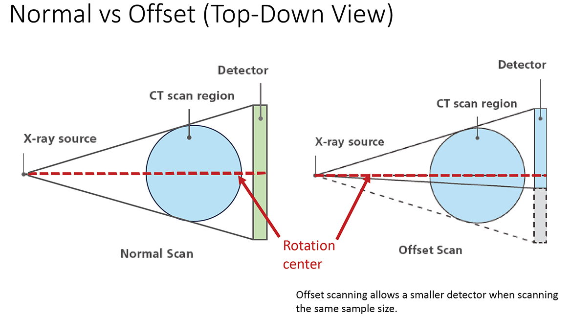
The tabletop CT scanner features include a 160 kV x-ray source and an efficient offset scanning geometry. With offset scanning geometry (figure 5) only half of the sample is scanned while being rotated 360 degrees. This shifts the rotation axis away from the detector center. The region of interest will be visible if it is projected onto the detector at some point within the 360-degree rotation. The projection data are combined and reconstructed to generate tomography images. Offset scanning geometry permits the use of a smaller detector which reduces both cost and signal processing time.
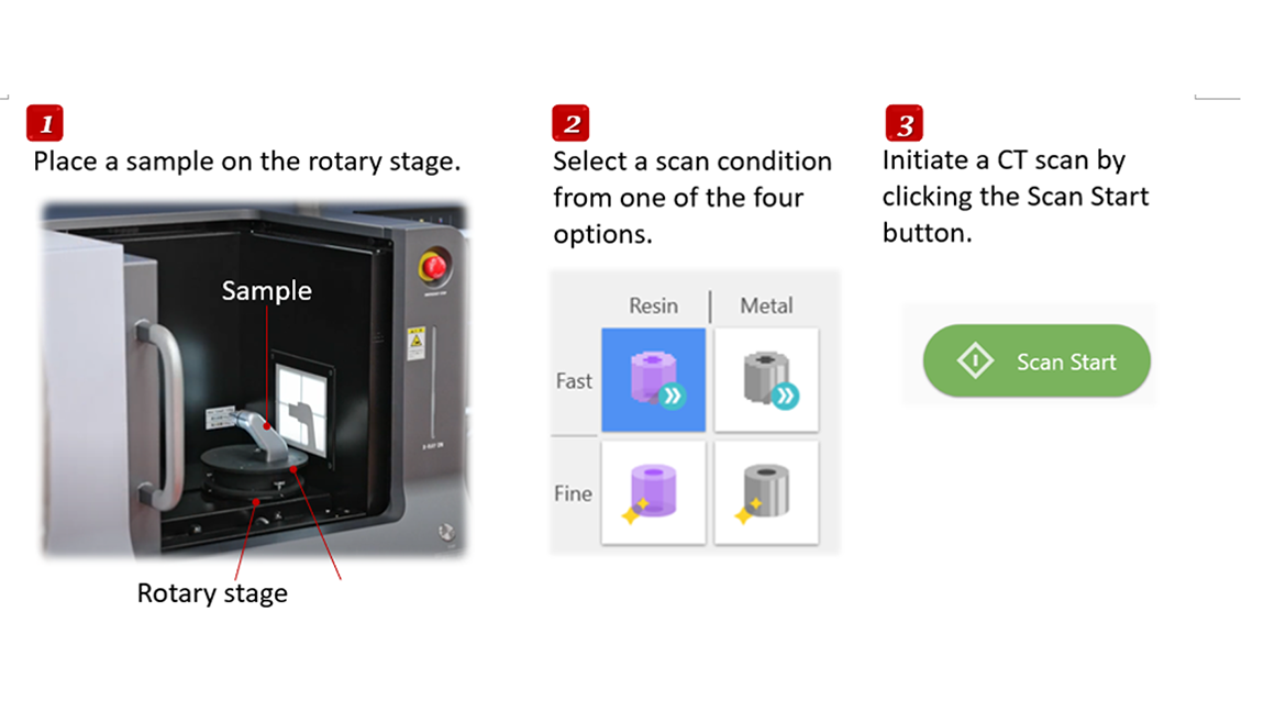
In addition, a novel, timesaving, data acquisition and processing scheme whereby the data acquisition and image reconstruction occur in parallel has been incorporated (Figure 6). A simplified data acquisition menu with only four preset analysis conditions: High or Low material density (Metal or Resin), and High or Low resolution, serves to further simplify operation.
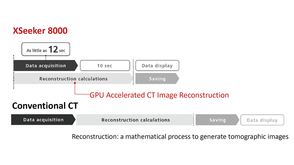
These features enable low-resolution images to be obtained in about 12 seconds for quick screening while higher-resolution images may be acquired in about five minutes for more detailed inspection. Figure 7 shows the simple and rapid steps to perform an analysis using this benchtop system. The design is particularly well-suited for rapid quality control screening to support manufacturing operations.
Application Examples
Aluminum die-cast part analysis
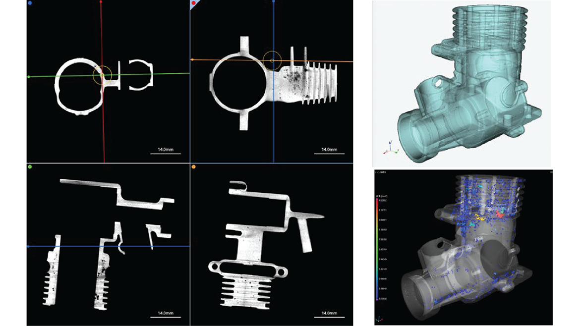
This is an example of internal defect analysis on a drone engine component made of diecast aluminum. In the slice and cross-sectional images, white areas depict aluminum castings; black spots represent defects such as voids. Volume rendering images enable visualization of defects’ three-dimensional characteristics.
Inspection of a motorcycle lamp
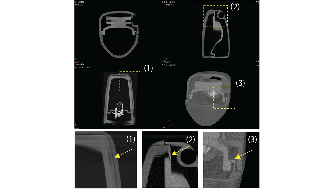
This example shows X-ray CT images of a failed motorcycle lamp. Areas of sealing damage that allowed water ingress are shown in the regions marked 1, 2, and 3. The alignment of the components is displayed in three dimensions.
Cable clamp
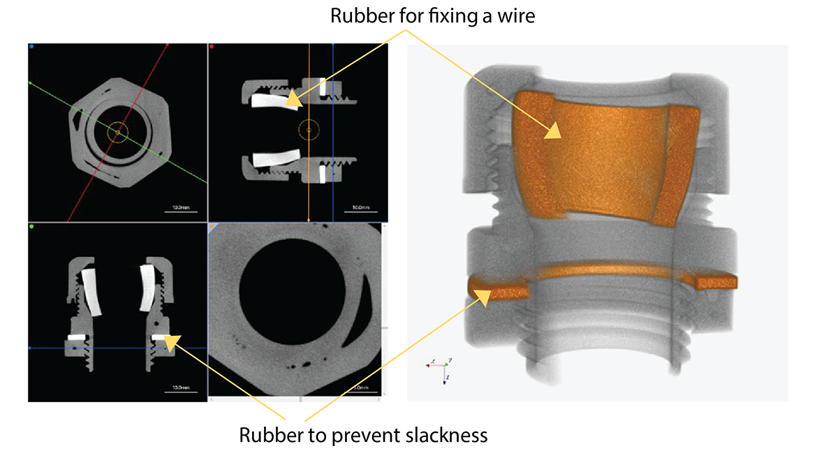
These X-ray CT images reveal the internal structure of a cable clamp in high-performance bicycles, verifying shapes, alignment of rubber parts, determining part count, and assessing fitment condition.
Summary
This brief introduction and examples show that tabletop X-ray CT scanning can be a rapid and powerful technique to nondestructively examine the internal features of materials. X-ray CT scanning can be especially helpful to support manufacturing processes where the final quality of the product can be adversely affected by internal defects.
Learn more about the compact, tabletop CT scanner used in these applications here: www.ssi.shimadzu.com/products/nondestructive-testing/microfocus-x-ray-ct-system/xseeker-8000/index.html
Looking for a reprint of this article?
From high-res PDFs to custom plaques, order your copy today!


