Software & Analysis
Practical Reverse Engineering
Choosing the right tools for the job.

Source: Verisurf
Digital reverse engineering (RE) as a concept has exploded in recent years due to advances in technology and a growing awareness of best practices among manufacturers. While its popularity continues to grow in many areas of design and manufacturing, there tends to be a perception of ‘one size fits all’ when it comes to RE solutions. From a practical perspective this perception is not accurate. Every RE project should be objectively evaluated to fully understand the intent and desired outcome, not only in terms of data requirements but the use of that data, in both upstream and downstream applications, to ensure digital continuity. This will help manage expectations and avoid frustration. RE is no different than any other project you might undertake: you need the right set of tools for the job.
In the big picture, RE is a subset of digital measurement, which is the driver behind other manufacturing applications, including quality inspection, tool building, and assembly guidance. When considering a digital RE strategy it is best to take a step back and look at your whole manufacturing enterprise, if for no other reason than to understand how choices you make might complement other applications or departments. Quite often companies have digital measurement assets available that are underused, thought to be outdated, or just forgotten. A perfect example is CNC CMMs. Most shops have at least one and many sit unused because they have old software and controllers or have been eclipsed by portable measurement devices. The fact of the matter is, these old devices are extremely accurate and well-built, and can be cost effectively upgraded to run the latest software.
Finishing The Job
When it comes to RE, customers are looking for end-to-end solutions, after all, the goal is to finish the job. To avoid the ‘one size fits all’ trap it is important to be objective and complete in your assessment process. There is nothing more frustrating than getting lulled into a partial solution or one that leaves you stranded on an island of incompatibility. When it comes to selecting your RE toolset it is important to lead with software. The software is what drives compatibility, workflow, processing, and digital continuity, also referred to as the manufacturing digital thread. Once you have your software platform in place hardware selection is dependent on your individual measurement requirements – scanning, probing, etc. Be sure your selected software is universally compatible to support and drive all legacy and new CMMs on the market.
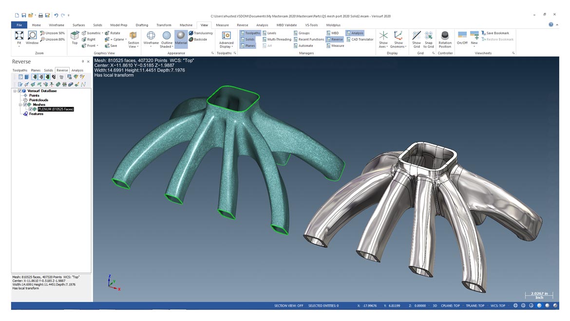
Quick Surface is an optional tool that quickly creates high-quality surfaces from scanned meshes or STL files. The software maintains curvature continuity between adjacent surfaces and is ideal for creating smooth, freeform CAD surfaces, ideal for high-speed toolpaths, either from organic or prismatic meshes. Source: Verisurf (Click on image to enlarge.)
Selecting The Right Measurement Device
Some RE software only supports offline applications where the measurement data is supplied as a download, and the capture process is left up to the individual measurement device typically driven by its own software. Others can drive the device, taking the measurement data directly into the application for processing and if preferred, they can work with offline supplied data as well. Selecting a device, regardless of format, with broad support for your chosen RE software is important. Preferably, access to a variety of device types will provide added flexibility to your overall RE strategy. The following questions should be considered during device selection:
- What is the size of the part being measured?
- Is the part prismatic or made up of complex surfaces?
- What is the intended result, watertight STL file, single machinable surface, or full CAD model with associative GD&T for manufacturing?
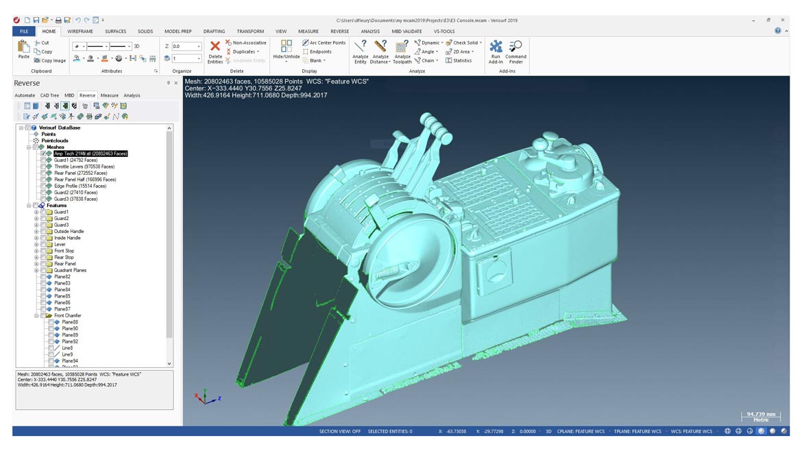
A complex profile scan was used to aid in the reverse engineering and development of a legacy Boeing E-3 Sentry throttle quadrant for use in flight simulator training. Verisurf Reverse and Verisurf CAD software was used to isolate features and create an exact tactile replica. Source: Verisurf (Click on image to enlarge.)
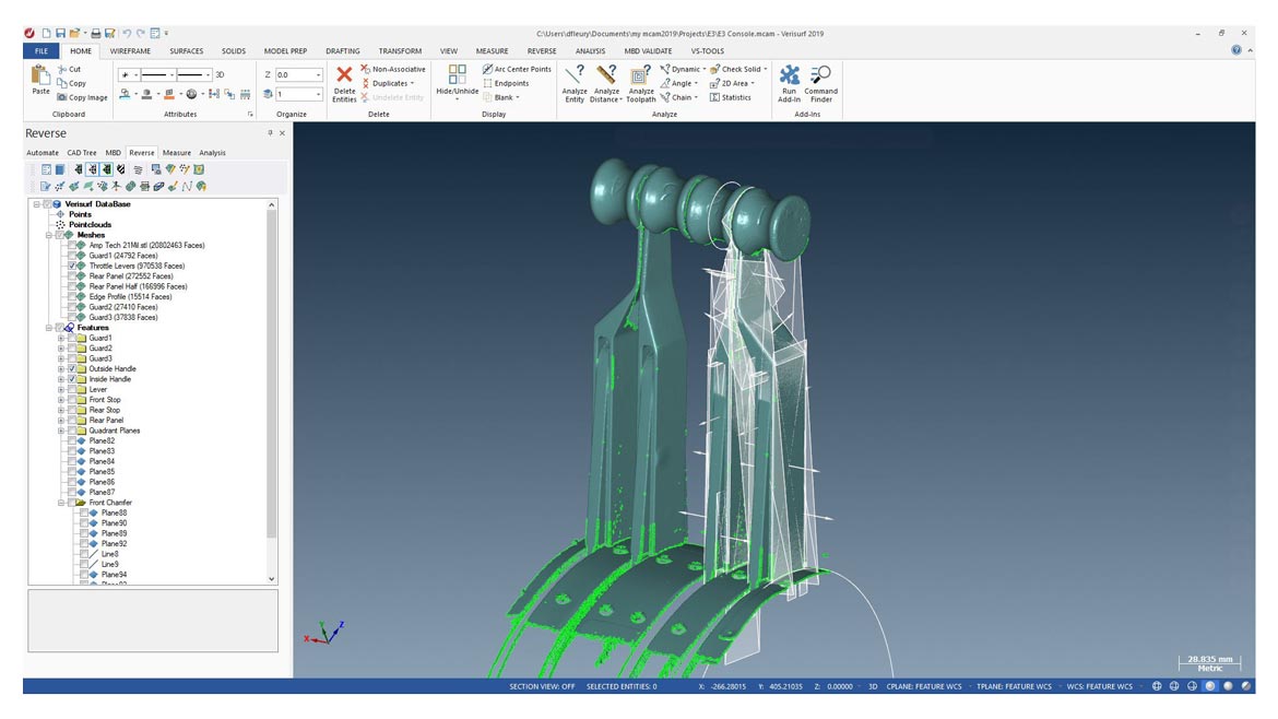
Software was used to isolate throttle levers and guide plates from the original surface profile scan. Note planes and edges highlighted for capture of geometry and conversion to CAD. Source: Verisurf (Click on image to enlarge.)
Sometimes, for example when reverse engineering complex assemblies, the answer is a combination of measuring devices. Possibly laser scanner, a touch probe system and even some good old fashioned CAD drafting.
Ask For Help
To avoid potential pitfalls, choose a software vendor that understands your processes and is willing to consult with you to provide the best and most complete solution right up front. There are some important considerations that should be brought to light during this process.
What are you trying to do? Not all RE software applications are the same, in fact some are quite limiting in their ability to create manufacturable parts. If you are simply looking for a 3D scan-to-print application without any real intelligent data, your solution choices are broad and straightforward. But if your end goal is a 3D CAD model complete with intelligent GD&T that can be inspected against the original artifact measurements, you should be considering a comprehensive measurement solution. One with the right application tools for the job.
What type and amount of data do you need? Many of today’s software solutions are capable of processing large measurement sets containing hundreds of millions of points, and computer processing and measurement device capabilities are also able to keep up, however, this is not always the practical approach. A more sensible approach might be to collect only as much data as you need to solve for the given project at hand. Huge point clouds of data are not always necessary to get the results you need. If you are reverse engineering a prismatic part, most likely using a touch probe vs. a scanner will be faster in the end and far more efficient when it comes to data management, workflow, and overall processing. To support a long term RE strategy, consider flexibility when choosing your software. A software solution that will work with and drive all measurement devices, create, and share intelligent CAD files, and provide quality verification for all reverse engineered parts produced will help you avoid roadblocks that can keep you from finishing the job.
RE With MBD
You hear a lot today about concepts like digital thread, digital twin, SPC, PLM, etc. Depending on the size of the organization, types of customers or supplier requirements, they can all be important initiatives, but the one thing they have in common is Model-Based Definition (MBD). Intelligent GD&T definitions are the foundation of every CAD model to define its design intent. If this is your end goal when it comes to digital RE then you should consider a software that is based on a CAD platform and has the right tool set to go from beginning to end, from measurement input through manufacturing and quality verification. This is where CAD based measurement software extends typical RE into practical RE for manufacturing.
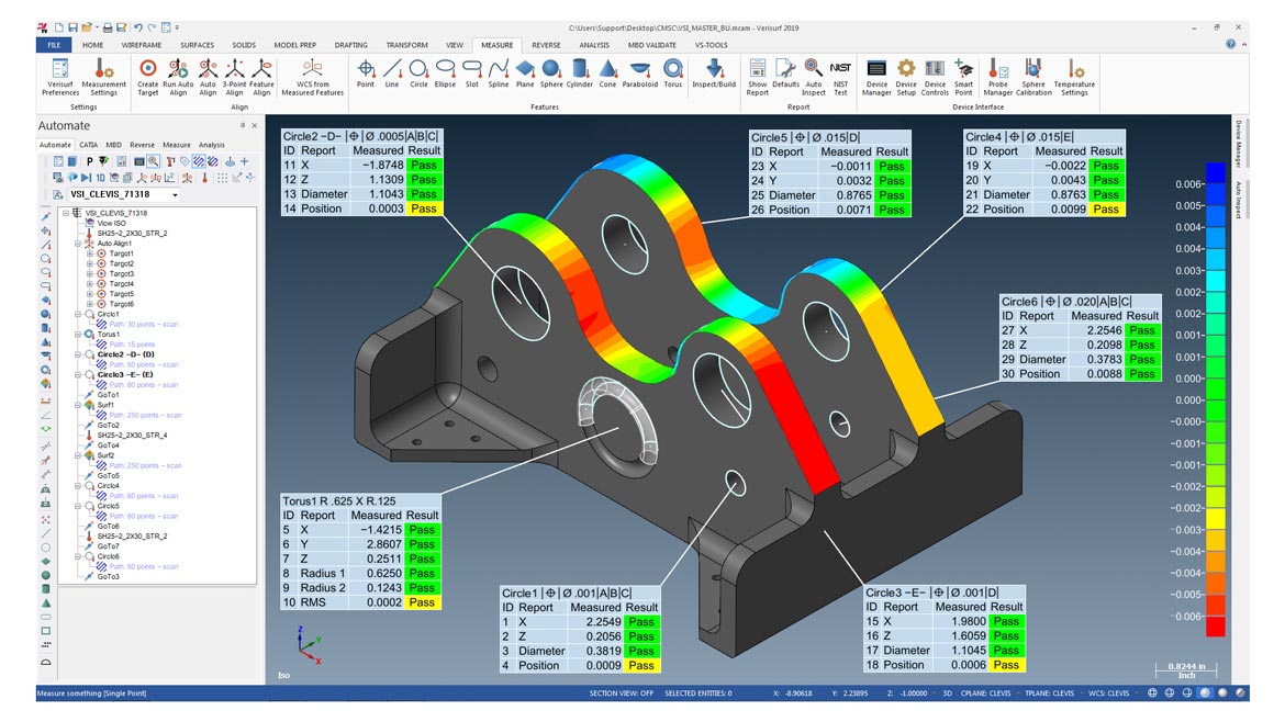
When the product definition flows from the reverse engineered CAD model through inspection and reporting, the integrity of the quality assurance process is maintained, closing the loop on design intent and implementation by feeding back to the 3D CAD authority. Source: Verisurf (Click on image to enlarge.)
CAD based RE software solutions with direct access to integrated inspection tools support model-based inspection using GD&T data. When the product definition flows from the reverse engineered CAD model through inspection and reporting, the integrity of the quality assurance process is maintained, closing the loop on design intent and implementation by feeding back to the 3D CAD authority.
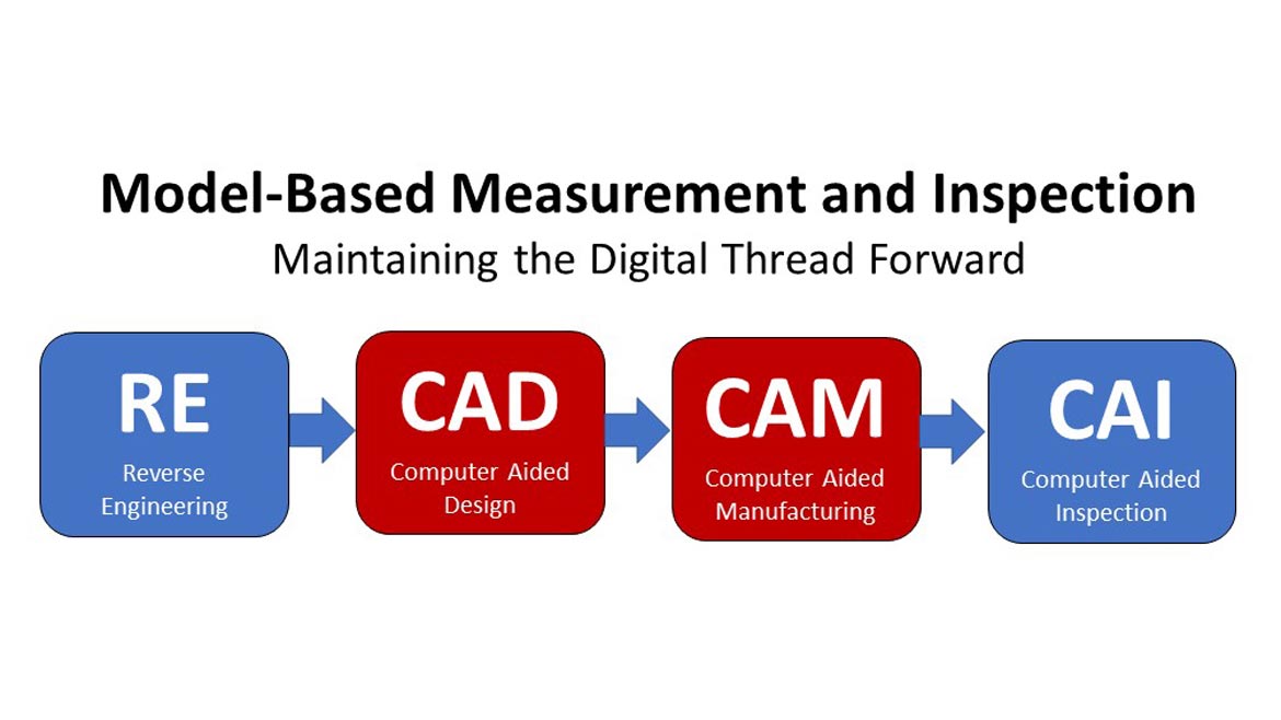
Moving The Digital Thread Forward
Through the practical implementation of model-based inspection, using intelligent GD&T definitions, the last fundamental manufacturing process, inspection, is now digitally connected, providing both immediate and considerable downstream benefits, including first article inspection (FAI), and feeding statistical process control (SPC) applications to proactively catch parts trending out of tolerance, before they become scrap.
Verisurf Reverse software is based on a CAD platform and is committed to model-based definition, using intelligent GD&T to feed manufacturing processes, and compare the final CAD authority and finished parts back to the original artifact. Source: Verisurf (Click on image to enlarge.)
Things To Consider (Avoid Pitfalls)
Making sure your RE software of choice complies with the following will help you deploy a metrology strategy that is more likely to support your manufacturing enterprise, and avoid challenges that can keep you from effectively completing RE projects:
- If possible, a single measurement software platform should drive all metrology processes across your manufacturing enterprise, including digital RE. This will reduce software maintenance costs, streamline education, provide a consistent database, and streamline human resource utilization
- Consider a CAD-based RE software to allow flexibility in managing files and easily accessing datums within the design authority
- When working alongside other design software be sure your chosen RE software can import and export ALL CAD files and models seamlessly for universal compatibility
- Make sure your RE software supports and drives all legacy and new measurement hardware, including touch probe devices, laser scanners, and trackers for maximum flexibility of data capture
When selecting the right digital RE toolset, remember that not every tool looks like a hammer. Understanding your unique requirements and making educated choices is quite often the difference between adoption and expansion of the technology with an organization and frustration and failure. Choose wisely.
Looking for a reprint of this article?
From high-res PDFs to custom plaques, order your copy today!


