Vision & Sensors | Machine Vision 101
Advancements In Telecentric Technology
As telecentric lenses become more compact, the overall footprint of vision systems will follow.
Image Source: MrKornFlakes / iStock / Getty Images Plus via Getty Images
The discipline of machine vision encompasses imaging technologies and methods to perform automatic inspection and analysis in various applications, such as verification, measurement, and process control. Driven by trends in Industry 4.0, machine vision has grown steadily over the past few years and now covers a wide range of applications in the most disparate sectors: from automotive to pharma, from food and beverage to electronics. Practically no sector has been left out of this transformation.
Generally, it is possible to distinguish between two main types of machine vision applications:
- Inspection, which involves shape or color defect detection, presence/absence and position checking, and barcode reading.
- Gaging, which involves passing from traditional systems to noncontact optical measurement.
It is in the latter that telecentric optics boast performance primacy when compared to standard entocentric, fixed focal length lenses. The reason lies essentially in the optical design: While entocentric lenses accept a diverging cone of rays (i.e., they work like our own eyes or the camera of a smartphone), telecentric lenses accept only collimated ray bundles (i.e., rays that are parallel to the optical axis). Figures 1 and 2 show the difference between telecentric lenses and common optics.
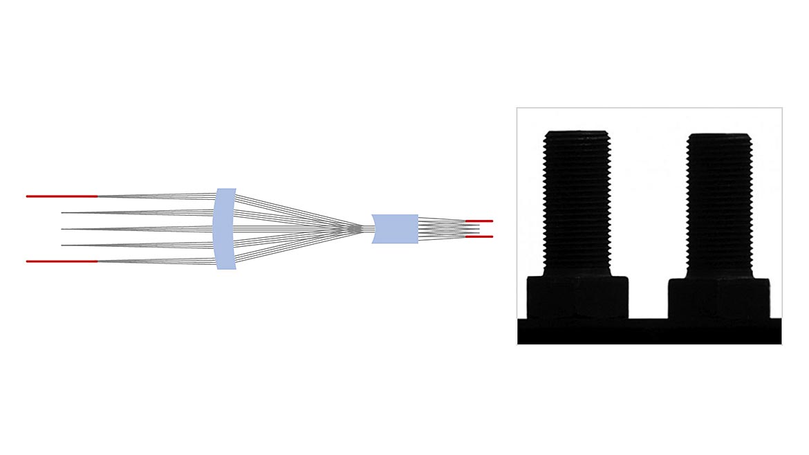
Figure 1. The design of a telecentric lens is such that similar objects at different distances from the lens appear to have the same size. All Figures Courtesy of Opto Engineering® (Click on the image to enlarge.)
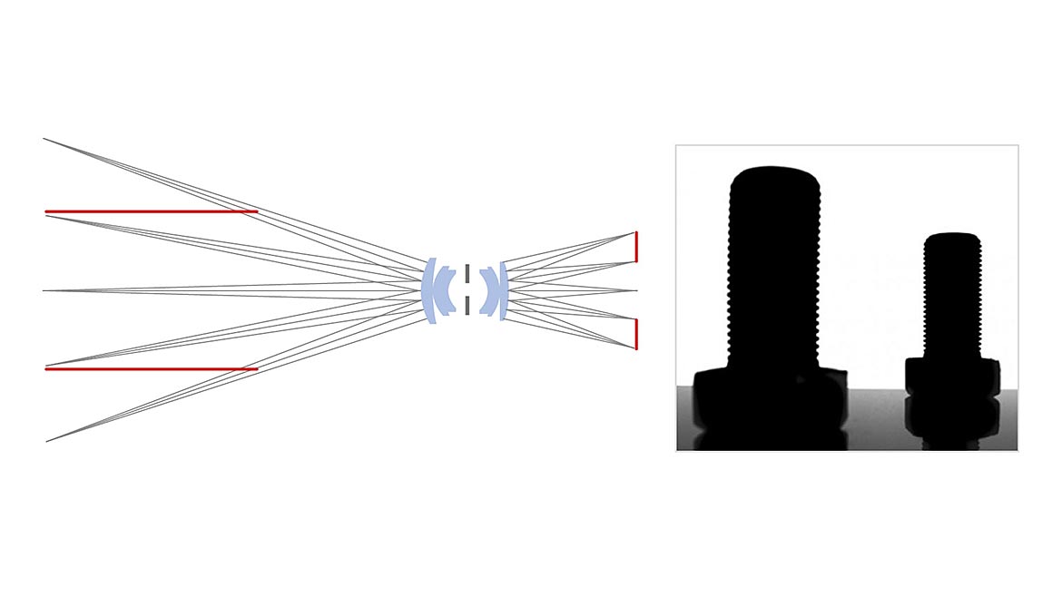
Figure 2. With entocentric optics, a change in the working distance is seen on the sensor as perspective error. All Figures Courtesy of Opto Engineering® (Click on the image to enlarge.)
Telecentric Lenses
This feature that is peculiar to telecentric lenses offers benefits for measurement purposes, starting with constant magnification; these lenses bring objects located at various distances into focus. While fixed focal length lenses can cover wide fields of view (FOVs), their magnification varies over working distances (WDs) and they are poorly suited to determining the true dimensions of an object. For example, images of two identical objects located at slightly different distances from the fixed focal lens will appear dissimilar and show an apparent (but not real) difference in dimensions (the greater the distance, the smaller the image) in exactly the same way our eyes work.
The elimination of perspective error is another important advantage of telecentric lenses and is particularly useful when thick objects such as tubes are imaged. Of course, this advantage holds true as long as the objects are in focus, which brings up another important point: Telecentric lenses feature a wide depth-of-field (DOF) region. Field depth is the maximum acceptable displacement of an object from its best focus position. Beyond this limit, the image resolution becomes poor because the rays coming from the object can’t create sufficiently small spots on the detector. A blurring effect occurs because geometrical information carried by the optical rays spreads over too many image pixels.
Because of their design, telecentric lenses also display very low levels of distortion. Distortion is an optical artifact that slightly changes the image dimensions of an object even if its distance from the lens doesn’t change. Low distortion makes telecentric lenses an excellent choice for measurement tasks.
The particular design necessary to obtain all of these features, however, has made telecentric lenses quite bulky when compared with standard entocentric lenses. In fact, as a rule, the diameter of the frontal element of telecentric lenses must be at least as big as the object to be imaged, since only rays parallel to the optical axis are accepted and the length of the lenses varies accordingly. Of course, because of a scale effect, the situation becomes critical when large FOVs are required.
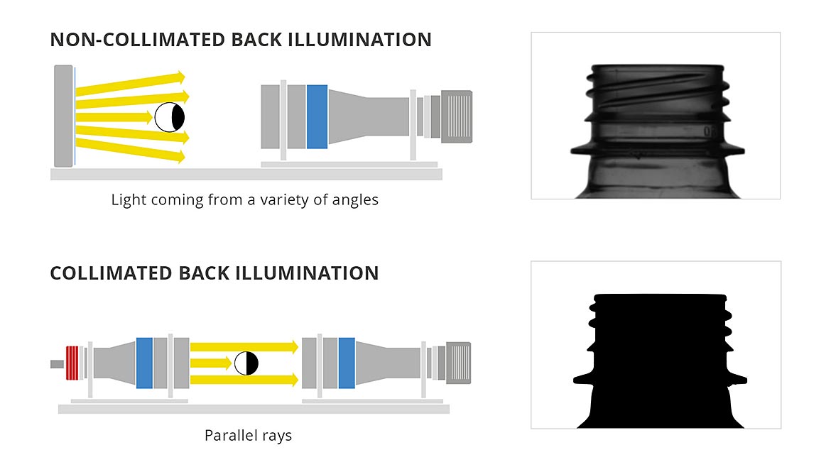
Figure 3. Collimated versus diffuse backlight illumination. Noncollimated back illumination, with light coming from a variety of angles (a); collimated back illumination, with parallel rays (b). All Figures Courtesy of Opto Engineering® (Click on the image to enlarge.)
Collimated Lights
To further improve the performances of the measurement system, telecentric lenses can be coupled with collimated illuminators (also called telecentric illuminators). The use of telecentric illuminators is required in several cases:
- Accurate edge-detection and defects analysis in silhouette imaging.
- High-speed applications, because high throughput — when combined with telecentric lenses — allows for only very short exposure times.
- Measurement of reflective cylindrical objects, because diffuse backlights can generate undesired reflections from the edges, making the objects look smaller than they are and leading to inaccurate measurements. Collimated rays typically are reflected less and thus eliminate this “border effect.”
The use of collimated light in combination with a telecentric lens brings two advantages (Figure 3). First, the DOF can increase up to 20% to 30%, even if there are several other influential factors, such as the type of lens, the wavelength of light, and the camera’s pixel size. Second, because of excellent light coupling, the distance between the object and the light source can be increased as needed without affecting image quality. These advantages, however, come at the expense of the overall footprint of the system: Bulk is doubled when coupling telecentric lenses and lights.
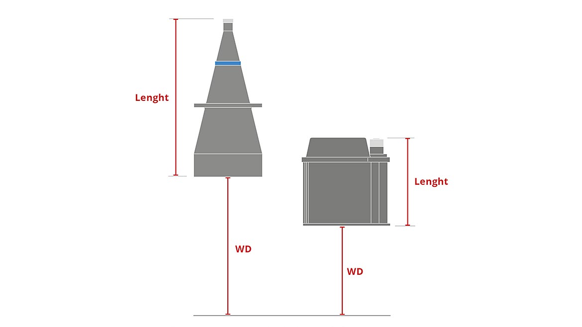
Figure 4. A comparison between a standard telecentric lens (left) and the compact version for the same FOV (right). All Figures Courtesy of Opto Engineering® (Click on the image to enlarge.)
Recent Advancements
Recent advancements in optical design have enabled the surmounting of limitations inherent in telecentric optics, creating ultracompact lenses and illuminators that drastically downsize the dimensions of vision systems (Figure 4). As is often the case, the inspiration comes from a different field — astronomy, and, specifically, telescopes, which provide a perfect example of very large FOVs imaged in a relatively small space.
Because of a catadioptric design, the overall footprint of a vision system can be reduced up to 50% with:
- A decrease in the physical dimensions of the optics.
- A reduction in the WD.
For example, a standard telecentric lens for an FOV of ~200 mm is ~600 mm long and has a WD of ~520 mm. A compact version for the same FOV would have a length of ~350 mm and a WD of 340 mm.
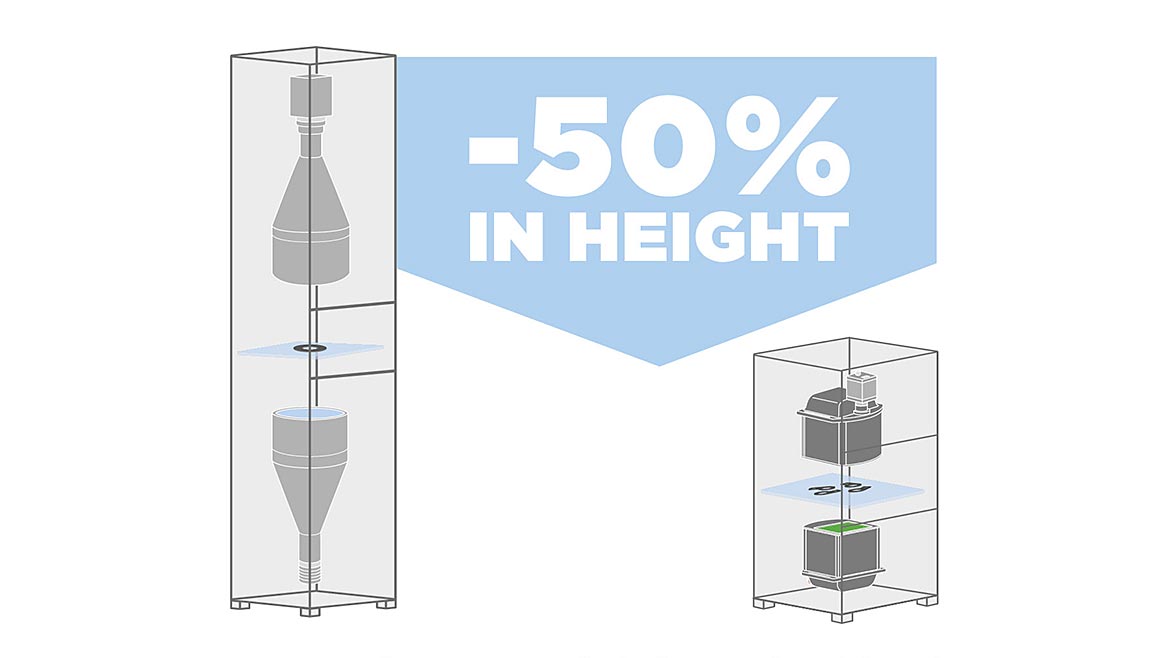
Figure 5. Comparison of precision measurement systems with “classic” telecentric lens and light VS compact version for the same FOV All Figures Courtesy of Opto Engineering® (Click on the image to enlarge.)
An even greater downsizing is possible with the combination of telecentric lenses and illuminators, since the effect is doubled. In fact, the overall footprint of the system can be reduced up to 50% (Figure 5) because of the perfect coupling of the light produced by the illuminator and the rays accepted by the lens.
Furthermore, when lightweight materials are accurately chosen and special attention is paid to the design process, the dimensions and the weight of the vision system can significantly decrease thanks to this new technology. In fact, combining the aforementioned lightweight materials with the capability to directly clamp lenses and illuminators, without the need for dedicated complex and heavy mechanics, the overall weight of the system can be halved.
The perfect synthesis of a smaller overall footprint with reduced weight gives these new ultracompact telecentric lenses significant advantages. Manufacturing costs are reduced thanks to lower material consumption and because installation is easier and cheaper. The space requirements are greatly reduced for both storage and use. Moreover, shipment expenses and transportation risks decrease significantly because of the smaller size.
Finally, this new technology enables telecentric systems to fit in many places where it was once impossible. Before, suboptimal solutions were often used, including partial imaging of the sample, multilens systems, or movement of the sample/lens. These measures are no longer required with the advent of ultracompact telecentric optics.
Importance Of Calibration
Nothing comes for free, however, and in this case, there is also the other side of the coin to consider. Any real lens introduces some geometric distortion that is generally radially symmetric, as a reflection of the radial symmetry of the optics. The two main kinds of radial distortion are barrel and pincushion. With barrel distortion, the magnification of the image decreases as the distance from the optical axis increases, giving the impression that the image is wrapped around a sphere. With pincushion distortion, magnification increases with the radius, thus lines that do not pass through the center of the image are bent inward like the edges of a pincushion.
These concepts apply for both telecentric and entocentric lenses, in general, but because of the innovative optomechanical design of these new ultracompact optics based on curved mirrors, the arising distortion is not radial, nor does it display any kind of symmetry. This can be an issue when dealing with precise measurement applications, where a calibration of the lens is needed to achieve the desired performances. In fact, despite the very low levels of distortion with telecentric lenses, this value must be as close to zero as possible to achieve optimal results. Traditional algorithms are based on the assumption that the distortion is radially symmetric, which can be expressed as a function of the distance from the optical axis:
dist(R)=a+b∙R+c∙R2+⋯
Because this is not the case for these more compact lenses, a different approach must be used. Recently developed calibration tools can perform a correction of the acquired image based on a local remapping without, for example, any assumption on the shape of the distortion. For instance, from a single picture of a chessboard pattern covering the whole FOV, it is possible to obtain all the information needed to get rid of distortion. The typical procedure can be planned as follows:
- Acquisition of a single image of the calibration pattern (offline).
- Creation of a distortion map from the picture (offline).
- Saving of the distortion map on a reference file (offline).
- Correction of the distortion on every new image acquired, recalling the saved distortion map (online).
Future Perspectives
The advancements discussed open a wide range of new possibilities for telecentric optics. With extreme compactness, reduced weight, and excellent optical performances, these new lenses and illuminators can solve numerous tasks that were previously unthinkable. Furthermore, the design concept behind these optics can be exploited to expand the range of FOVs virtually infinitely. Finally, the concurrent advancements in software pave the way for a future in which its symbiosis with hardware will drastically extend the range of possible uses.
Looking for a reprint of this article?
From high-res PDFs to custom plaques, order your copy today!


