VISION & SENSORS - MACHINE VISION 101
Engineered Lighting: Part 2 of 3
Learn how to choose a light source to take advantage of the characteristics that create contrast.
Background: Stanislav Gvozd/iStock / Getty Images Plus via Getty Images. Lens: Moritex North America, Inc. Ring Light: CCS America.
Introduction
Part 1 of this three-part series examined how to identify characteristics of the object and the background you can use to create contrast with the illumination source for your machine vision application. This second part looks at how you go about choosing a light source to take advantage of the characteristics that create contrast.
Front-Lighting Or Backlighting?
Front-lighting is created when the camera and the light source are on the same side of the scene. When the light source is on the opposite side of the scene from the camera, it is backlighting.
For backlighting to work, certain conditions must be met:
- The background must be transparent or absent.
- The part must be opaque or have internal features of interest that are opaque or scatter or refract the light.
- There must be space to mount the backlight.
Although backlighting can give the highest contrast and should be used where practical, it does not work for many applications. The only other choice is front-lighting.
Directed Or Diffuse?
Light sources span the range from very directed to very diffuse (see Figure 3). Directed light sources tend to create shadows and make surface texture stand out in the image. Diffuse light sources tend to suppress shadows as well as suppress texture in the image.
Think of the most directed source imaginable: light that comes from a point source. It casts strong shadows with sharp, well-defined edges. Texture consists of random highlights and dark shadows. The spot light is a good example of a strongly directed light source.
Diffuse light sources tend to be large in area so any point in the scene receives light from a wide range of angles.
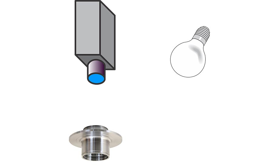
Figure 1. Front-lighting. Source: Automated Vision Systems
Figure 2. Backlighting. Source: Automated Vision Systems
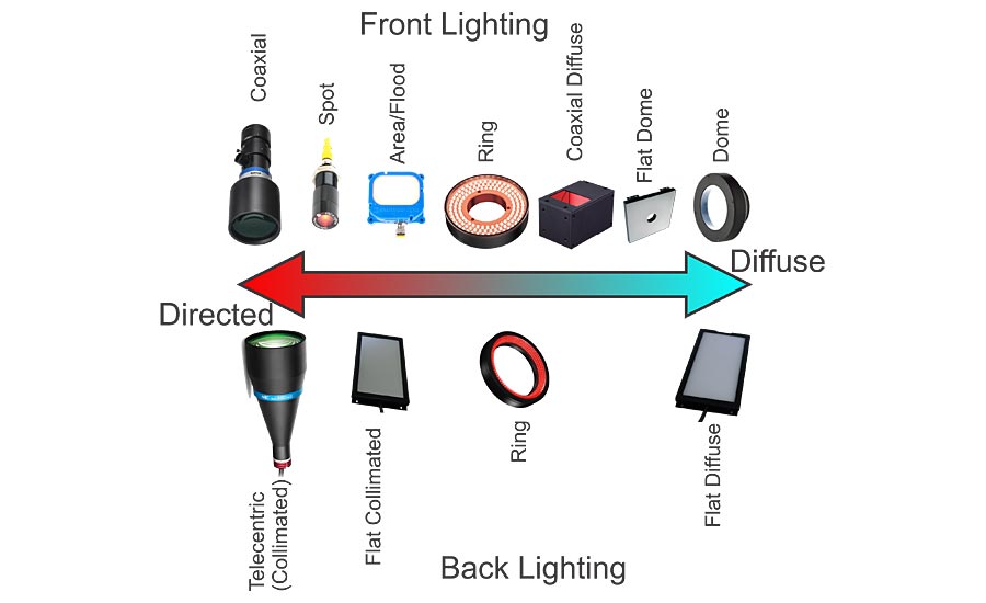
Figure 3. Light Sources, Directed Through Diffuse. Source: Automated Vision Systems
Brightfield Or Darkfield?
The definition of bright-field illumination and of dark-field illumination is very precise. In practice though, the actual differentiation is somewhat less precise.
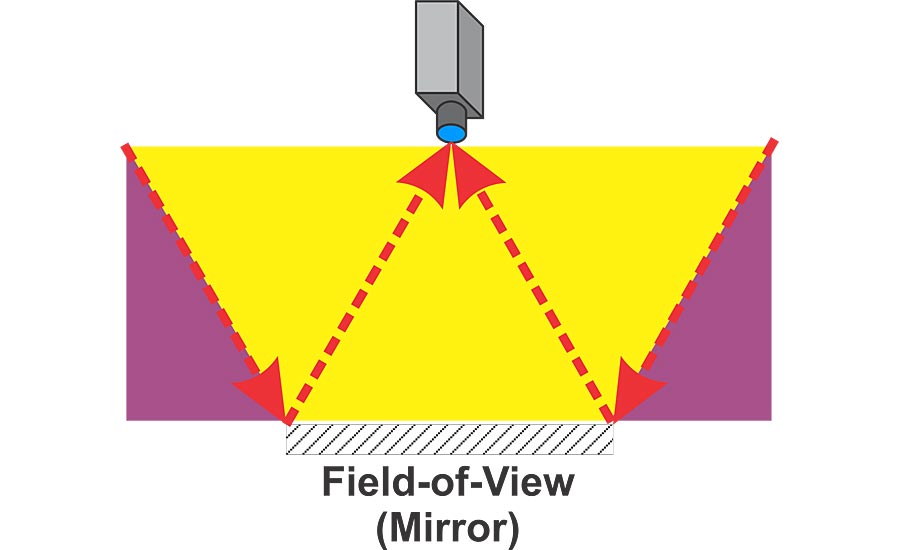
Figure 4. Front Lighting Showing Bright Field (Yellow) and Dark Field (Purple). Source: Automated Vision Systems
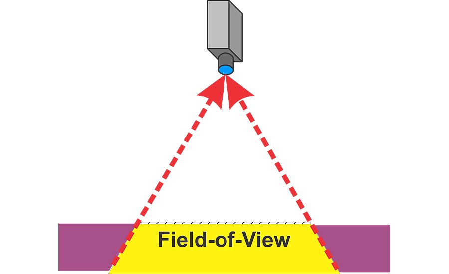
Figure 5. Backlighting Showing Brightfield (Yellow) and Darkfield (Purple). Source: Automated Vision Systems
In front-lighting there is the illumination “W” shown in Figure 4. The definition of brightfield assumes a camera and lens are imaging a flat mirror. The imaging forms a “W” when the edges of the field-of-view are reflected off the mirror. Any light source placed within the “W”, shown as yellow in Figure 4, reflects off the mirror directly into the camera. Thus, the light source is visible (bright) in the camera’s image.
Lights placed outside the “W” are not imaged by the camera, and the camera’s field-of-view is dark.
That’s the definition. In most instances, the camera is not imaging a polished surface such as a mirror. Light sources placed in the dark-field part of the illumination “W” and imaging diffuse surfaces will have some of the light energy imaged by the camera.
There is a similar situation for backlighting called the illumination “V”. This is shown in Figure 5. Notice, though, the “V” is actually inverted. Backlights placed inside the “V”, the yellow region in Figure 5, are imaged by the camera. Backlights placed outside the “V”, shown in purple in Figure 5, are not imaged directly by the camera.
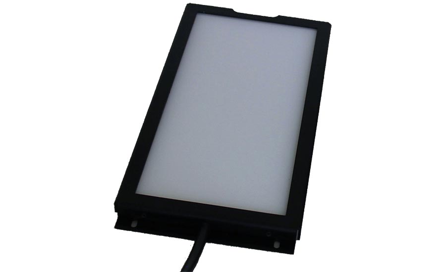
Figure 6. Flat Diffuse Backlight. Source: Advanced Illumination, Inc.
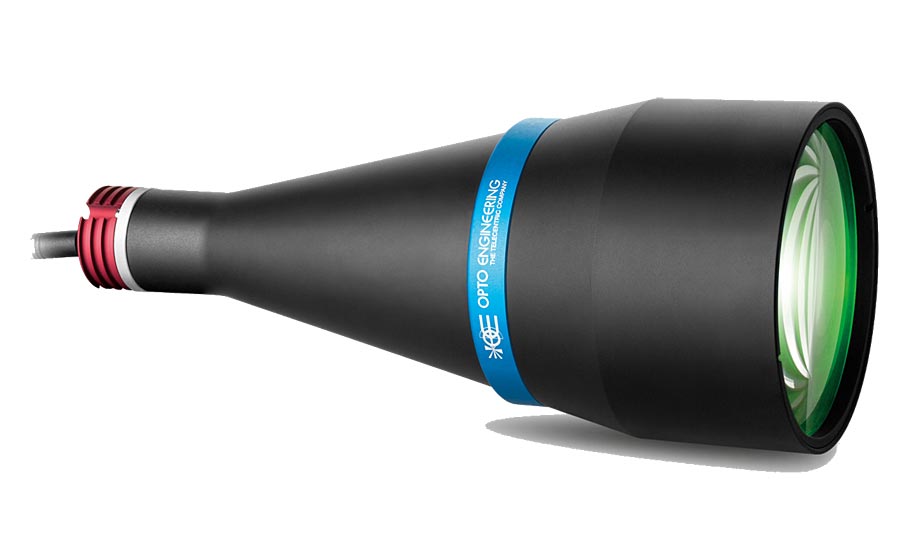
Figure 7. Collimated Back Light. Source: Opto Engineering United States
Backlighting Methods
Brightfield Backlights
Flat Diffuse Backlight
Flat diffuse backlights (see Figure 6) are the most common backlights in use. They work well for opaque objects and also with all types of machine vision lenses. Flat diffuse light sources are available in a very wide range of sizes to accommodate very small to very large fields-of-view.
One drawback of the diffuse backlight is, because of the wide range of angles over which the light is emitted, it also illuminates the edges of objects. For thin objects, such as flat sheets of metal, this is not a problem. For thicker objects where high accuracy measurements are needed, the illumination of edges can be problematic.
Collimated Backlight
Collimated backlights (see Figure 7) are a telecentric lens projecting an image of a light source. All of the emitted light rays are virtually parallel. This eliminates the problem caused by diffuse backlights where they illuminate the sides of objects.
Because light rays from a collimated backlight are parallel, the camera’s lens must have an aperture at least as large as the field-of-view. This tends to limit the use of collimated backlights to work best with telecentric lenses. Collimated light sources are physically large and heavy, especially for larger fields-of-view, and they are more expensive than other light sources.
The collimated backlight works well for opaque objects. It also works well for transparent objects such as bottles where, due to refraction of the light rays, the edges appear dark. It also works for imaging defects, like air bubbles and other inclusions in transparent objects, since the air bubbles also refract the light and become dark.
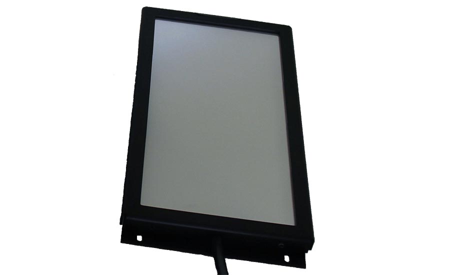
Figure 8. Flat Collimated Back Light. Source: Advanced Illumination, Inc.
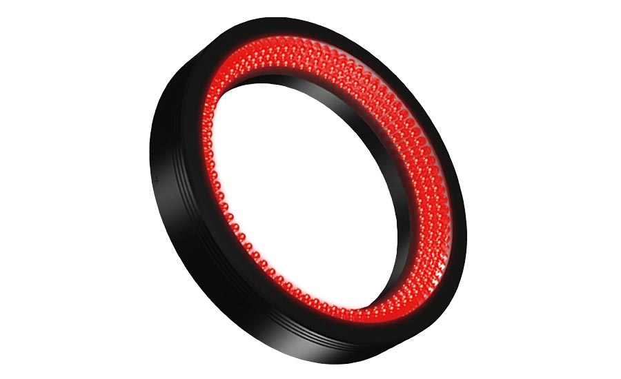
Figure 9. Dark Field Ring Light. Source: CCS America
Flat Collimated Backlight
The flat collimated light source (see Figure 8) looks very much like a flat diffuse light source. In fact, it is almost the same except for the introduction of one or two layers of film that narrow the emitted angle of the light rays. So, flat collimated backlights are not really collimated, the emitted rays are not parallel, but they emit light over a much narrower range of angles than the more common flat diffuse backlights.
The flat collimated backlight significantly reduces the light reflected off edges of an object that is problematic with flat diffuse backlights.
Because the light rays do spread out over an angle, the flat collimated backlight is not limited to work with telecentric lenses. Ordinary factory automation lenses can work with these lights provided the angle-of-view of the lens is limited. This may mean a longer working distance for a given field-of-view.
Dark Field Backlights
Ring Light
The choices in dark-field backlights are very limited. The primary light source is the ring light with its LEDs arranged to focus inward where the light is placed outside the camera’s viewing angle as shown in Figure 9.
A dark-field backlight is appropriate for picking up defects in transparent objects.
The ring light is usually much larger than the field-of-view, and care in selection and application of the light source is needed to insure reasonable uniformity across the field-of-view.
The spotlight (see Figure 10) is used only in rare situations for dark-field back lighting. This is due to the light fall-off as the inverse square of the distance from the light. It is not possible to get uniform lighting with a spotlight. Uniformity is improved by moving the spotlight as far away from the field-of-view as practical.
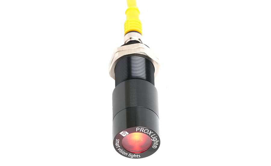
Figure 10. Spot Light. Source: Smart Vision Lights
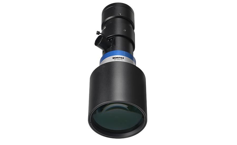
Figure 11. Telecentric Lens with Port for Coaxial Illumination. Source: Moritex North America, Inc.
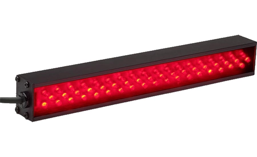
Figure 12. Bar Light. Source: Advanced Illumination, Inc.
Front-Lighting Methods
Bright-Field
Coaxial Illumination
Some telecentric and macro lenses are available with coaxial illumination – illumination projected through the lens itself. Figure 11 shows a macro lens with a port for a light source midway up on the right side of the lens.
This lighting method produces very good images when imaging shiny (specular or semi-diffuse surfaces), flat surfaces against a surface with different reflectance properties. Like most directed sources, it does not work well for surfaces that are curved or have slope differences unless the purpose is to differentiate the slopes.
Spotlight Illumination
Spot lighting (see Figure 10) is used when it is desired to create strong, dark shadows from height differences or from texture. Because spot lighting creates non-uniform illumination unless it is positioned a good distance from the field-of-view, its use in machine vision has been limited.
Area Or Flood Lighting
A light source often used in machine vision is the area light. This provides directed lighting over a wider range of angles than the spotlight and gives somewhat softer shadows and textures. The most common arrangement is the bar light.
Bar lights are available in a wide range of lengths and widths to fit many applications. Often bar lights are used in pairs to help create more uniform illumination.
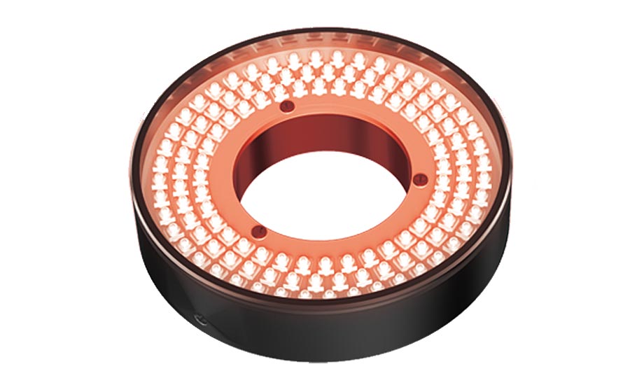
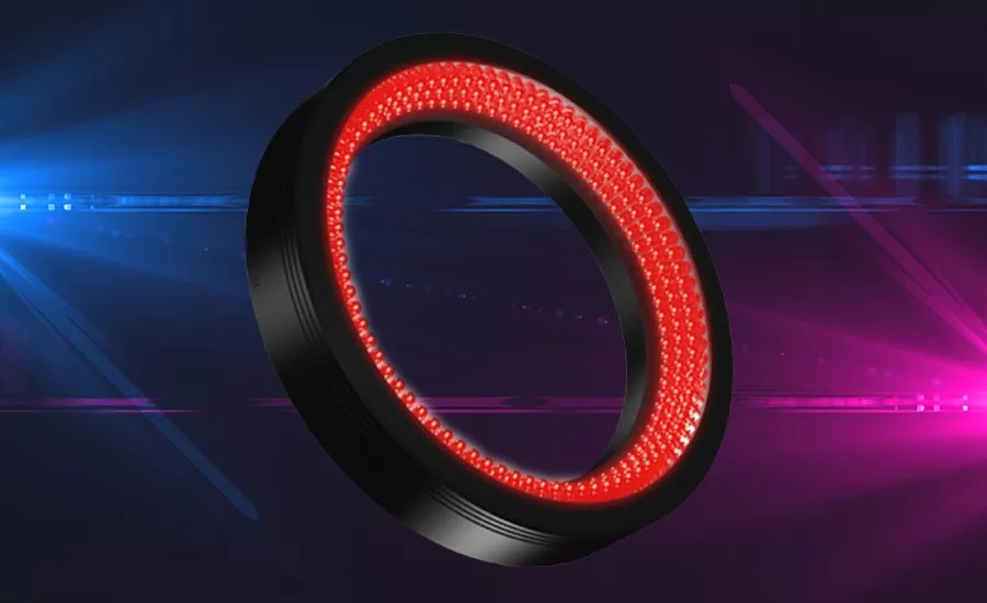
Figure 13. Ring Light. Source: Automated Vision Systems
Figure 14. Coaxial Diffuse Illuminator. Source: Automated Vision Systems
Ring Light
The ring light is perhaps the most common front light used in machine vision (see Figure 13). It is available in a wide range of sizes and light colors. Each ring light is design for a maximum field-of-view and a range of working distances. If the field-of-view is too large or the working distance is too close or too far, uniformity of illumination is compromised.
Coaxial Diffuse
The coaxial diffuse light source (see Figure 14) is the first of the diffuse light sources for front lighting. The light source is placed so the camera views through the light source and the light is in the same general direction as the imaging.
The differences between coaxial lighting and coaxial diffuse lighting is the coaxial diffuse light is external to the lens and light from the source reaches each point in the field-of-view from a wider range of angles than coaxial lighting.
Coaxial diffuse lights work best when they are larger than the field-of-view and relatively close to the field-of-view. As the coaxial diffuse light moves further away from the field-of-view, its light becomes more like coaxial lighting.
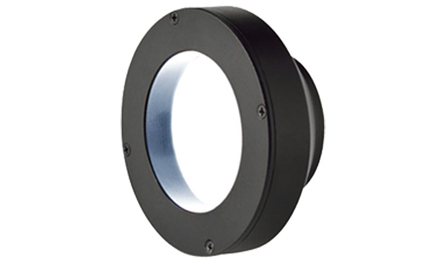
Figure 15. Dome Light. Source: Omron Corporation
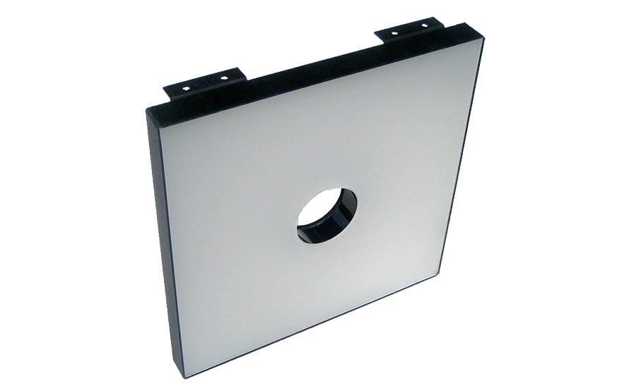
Figure 16. Flat Dome Light. Source: Metaphase Technologies Inc.
Dome
The dome light (see Figure 15) is the most diffuse light source available for machine vision. It uses a ring of LEDs around its periphery aimed, not at the part, but at the white diffuse interior of the dome. The result is illumination that floods the field-of-view with light from an extremely wide range of angles. Shadows become non-existent. Texture is not evident. Changes in surface angle have little difference in the light reflected into the camera. Even specular reflections, glints and glare, are dramatically suppressed to be almost eliminated.
The downside of the dome light, besides its expense, is it needs to be much larger than the field-of-view, almost two times larger, and it needs to be as close as possible to the part to have the wide range of light angles. So large size and restricted working distance are its biggest drawbacks.
Flat Dome
The flat dome light source (see Figure 16) is a compromise over the dome light. It’s basically the same as a diffuse backlight except with a hole in the center for the camera to view through. The flat dome’s advantage over the dome light is it gives increased working distance. Its light is not as diffuse as the dome light, the range of angles is not as great as a dome. Still, it does a very good job in suppressing shadows, textures, and glints and glare from the scene.
The flat dome light must be positioned near, or even around, the lens so its hole does not obscure the lens’ view. To work best, it must be larger than the illumination “W”. So, it becomes large in size.
Dark-Field
Ring
Most dark-field, front lighting is implemented with a ring light. However, dark-field ring lights differ from bright field ring lights in the orientation of the LEDs. In bright-field ring lights, the LEDs are directed more along the light’s axial direction (see Figure 9). In dark-field ring lights, the LEDs tend to be oriented more in the radial direction toward the center of the light.
To achieve uniformity of illumination across the field-of-view, dark-field ring lights need to be much larger than the field-of-view itself. A different approach is the use of four bar lights in a ring configuration. With the bar lights, the size can be somewhat smaller. Also, the bar lights’ angles are adjustable to obtain optimum illumination.
Spotlight
There are times when it is desirable to emphasize features in a certain orientation. In those instances, a more directed dark-field light, such as a spotlight (see Figure 10), may be the choice. The drawback is the non-uniformity of illumination across the field-of-view.
Looking for a reprint of this article?
From high-res PDFs to custom plaques, order your copy today!


