Test & Inspection
Structured Method Selection in Remote Visual Inspection of Machined and Fabricated Components
Selecting the appropriate method begins with defining what the inspection must accomplish.

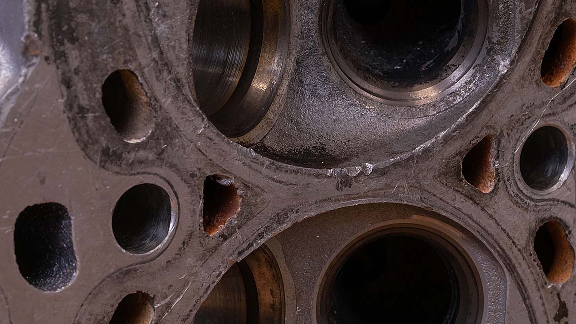
Pictured: Cross-section of machined metal casting component
High-value metal components produced through machining, casting, welding, and fabrication often contain internal features that cannot be evaluated by direct line of sight. Cross-drilled passages, internal weld roots, cooling channels, and deep bores conceal cracks, porosity, incomplete fusion, debris, or dimensional irregularities and are inaccessible without disassembly or destructive sectioning. In most quality environments, those approaches are impractical and cost prohibitive.
Remote visual inspection (RVI) provides a controlled method for examining these obstructed features while preserving component integrity. Its effectiveness depends less on selecting a particular device and more on following a disciplined evaluation sequence. Defining the inspection objective, understanding access constraints, and aligning image performance with documentation requirements are the essential steps in matching an RVI method to the inspection challenge.
Define the Inspection Objective
Selecting the appropriate method begins with defining what the inspection must accomplish. Establishing that objective requires evaluating two primary considerations: the area of interest within the component and the inspection application in which it will be performed. Without this definition, method selection becomes reactive and inconsistent.
The first consideration is the area of interest and the conditions that must be evaluated there. This may include an internal weld root, a machined bore surface, a cross-drilled passage, or a concealed structural feature within a fabricated part. The inspector is assessing whether the targeted surface meets defined acceptance criteria. Potential findings may include cracks, porosity, incomplete fusion, corrosion, foreign object debris, or dimensional nonconformances. Defining the area of interest establishes the level of image clarity and viewing control required for reliable evaluation.
The second consideration is the inspection application, or the operational purpose and conditions under which the inspection is performed. In-process verification may prioritize speed and repeatability, while final quality checks may require image capture and traceability. Failure analysis may demand closer examination and controlled viewing conditions. When the area of interest and inspection application are clearly defined, the technical requirements for RVI become clearer.
With inspection intent established, the next step is evaluating the physical constraints that govern access to that area.
Evaluate Access Constraints
With the area of interest and inspection application clearly defined, the next step is evaluating the physical constraints that govern access to that internal feature. In many RVI applications involving complex components, access limitations narrow viable options before image performance is considered.
Entry width or diameter is often the first constraint. When inspection requires insertion into a bore, passage, cavity, or welded assembly, the available opening determines the maximum probe diameter. Tightly machined access points or small cross-drilled passages may significantly limit tool selection and maneuverability. However, minimizing diameter should not automatically take precedence over image clarity or control.
Inspection depth also influences method selection. Internal features may be located deep within a casting or assembly, requiring extended insertion length and stable navigation. Illumination intensity, image stability, and control become increasingly important as depth increases.
Internal geometry further shapes method selection. Changes in direction, intersecting passages, recessed weld roots, or concealed surfaces may require articulation or alternative direction of view (DOV) to properly visualize the inspection area. Without an appropriate DOV, relevant conditions may remain undetected even when image resolution is sufficient.
Environmental conditions must also be considered. Residual machining fluids, debris, surface oxidation, or higher internal temperatures can affect inspection consistency. The selected RVI approach must align with these operating conditions to ensure reliable results.
Once the inspection objective is defined, physical access constraints must be evaluated.
Overview of RVI Method Categories
RVI methods vary in complexity and capability depending on access and performance requirements. Understanding their differences allows inspection teams to match method-to-application more effectively.
Optical extension tools represent the most basic form of remote viewing. Mirrors and magnifiers extend visibility into partially obstructed features without electronic imaging. These tools are simple, durable, and usually cost-effective. However, they cannot navigate enclosed or deep internal features, do not support image capture for documentation, and depend heavily on operator positioning and lighting conditions.
Fiberoptic borescopes transmit images through coherent fiber bundles from the inspection tip to the viewer. Illumination is delivered through surrounding light-transmitting fibers that project light onto the internal surface. Because no electronic sensor is housed at the distal end, fiber-based systems are often favored when access diameters are extremely limited. In applications where openings approach 2 mm or smaller, fiber probes may provide the most practical solution. However, image resolution is limited by fiber count, and the fiber bundle is susceptible to damage or breakage with repeated use.

Video borescopes incorporate a miniature CMOS image sensor at the distal tip and transmit the image electronically. Illumination is typically provided by integrated white LEDs, with UV sources used in specialized inspections; in very small probes, light may be delivered through fiber guides. Because the image sensor must be physically housed at the tip, the minimum diameter of a video borescope is constrained by the size and packaging of the CMOS sensor. As a result, video probes generally cannot achieve the same extremely small diameters as fiber-optic systems. When access openings are approximately 2 mm or larger, video-based systems become more broadly applicable and offer advantages in image capture, documentation, and adjustable viewing parameters.
Understanding these distinctions keeps method selection aligned with inspection objectives rather than familiarity or convenience.
Image Quality and Documentation Considerations
Once a method can access the inspection area, image performance becomes the determining factor in evaluation reliability. In confined features such as bores, weld roots, and internal passages, usable detail depends on more than sensor resolution alone.
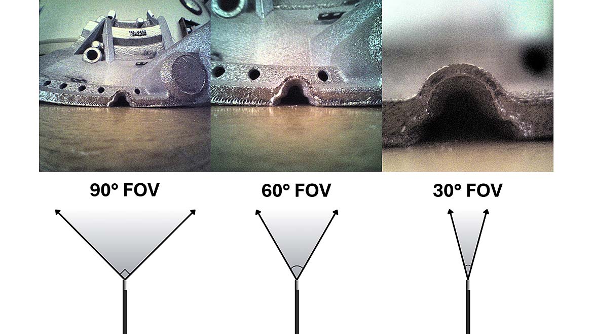
Field of view (FOV) directly affects inspection efficiency and defect visibility. A wider FOV increases surface area coverage and reduces repositioning time, provided resolution remains sufficient. A narrower FOV increases apparent detail but limits coverage and may require additional probe movement. Selecting the appropriate FOV requires balancing efficiency with the ability to resolve the smallest defect of concern.
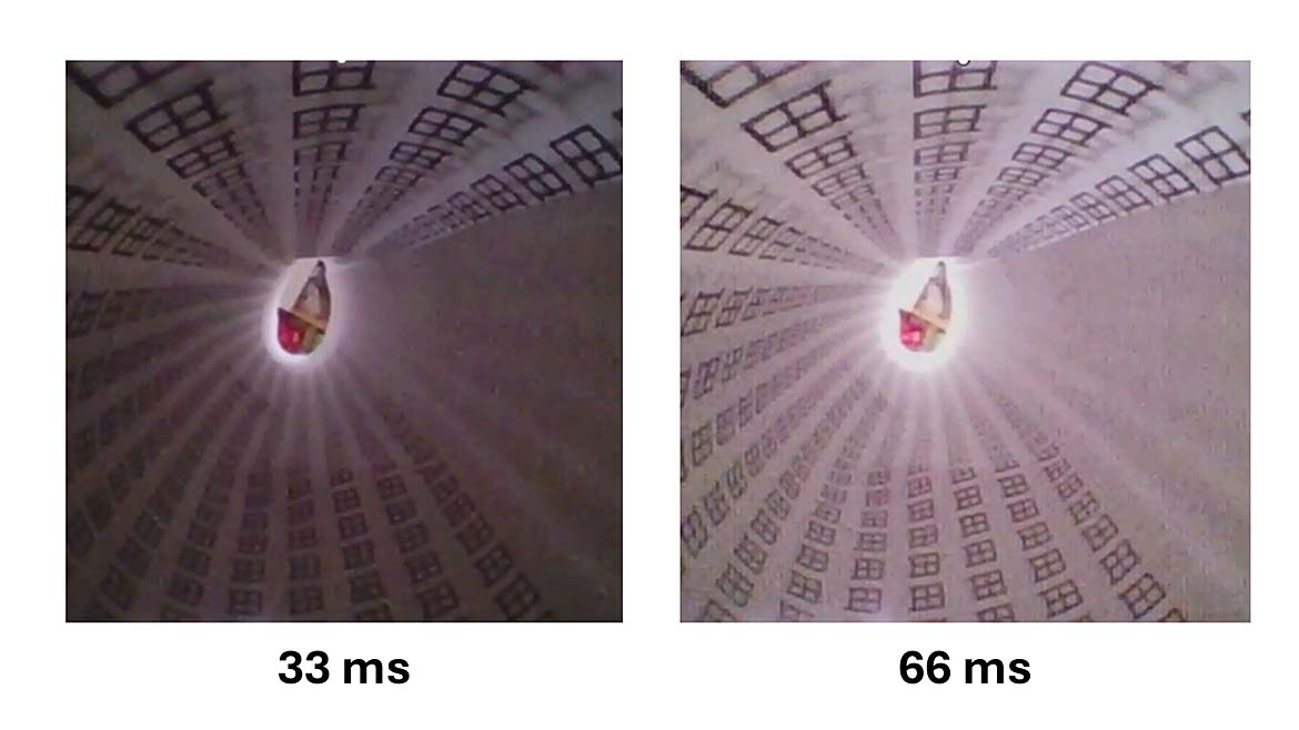
Depth of field (DOF), or the range within which surfaces remain acceptably in focus, is equally important in internal inspection. In geometries where tip-to-target distance varies, limited DOF can obscure fine cracks or porosity even when overall resolution is adequate. Maintaining proper DOF helps ensure that relevant features remain clear without excessive repositioning.
Illumination also plays a critical role. Insufficient light within deep bores or internal passages can obscure fine detail and compromise inspection accuracy. Reflective machined surfaces may also create glare if lighting is poorly controlled. Proper light intensity, balancing, and image processing are essential to ensure that surface conditions are represented clearly and consistently.
Effective RVI depends on integrating FOV, DOF, illumination, and documentation requirements to produce reliable, decision-grade images.
A Structured RVI Selection Framework
Selecting an RVI method is most effective when approached as a structured decision process rather than a technology preference. Challenges arise when probe diameter is prioritized without evaluating image performance, when resolution is emphasized without considering FOV or DOF, or when documentation needs are addressed only after equipment selection. In each case, the mismatch occurs because the solution is chosen before the problem is fully defined.
A disciplined sequence improves alignment. The process begins with clearly defining the internal area of interest and the applicable acceptance criteria. Access constraints such as entry diameter, depth, and internal geometry are then evaluated to determine feasible method categories. Only after access is understood should image performance parameters including FOV, DOF, illumination control, and documentation capability be assessed against the inspection objective.
By addressing the inspection challenge in this order, quality professionals can match method to application with clarity and efficiency. As internal features in high-value metal components grow more complex, effective RVI depends not on selecting the most advanced device but on systematically aligning access, image performance, and documentation with the inspection objective. When applied in this way, RVI becomes a reliable and repeatable component of the quality process.
Looking for a reprint of this article?
From high-res PDFs to custom plaques, order your copy today!


