Test & Inspection
Common Challenges and Keys to Success for Fatigue Testing of Additively Manufactured Metals
Additive manufacturing offers geometric freedom that was previously impossible, but it demands a higher standard of validation.
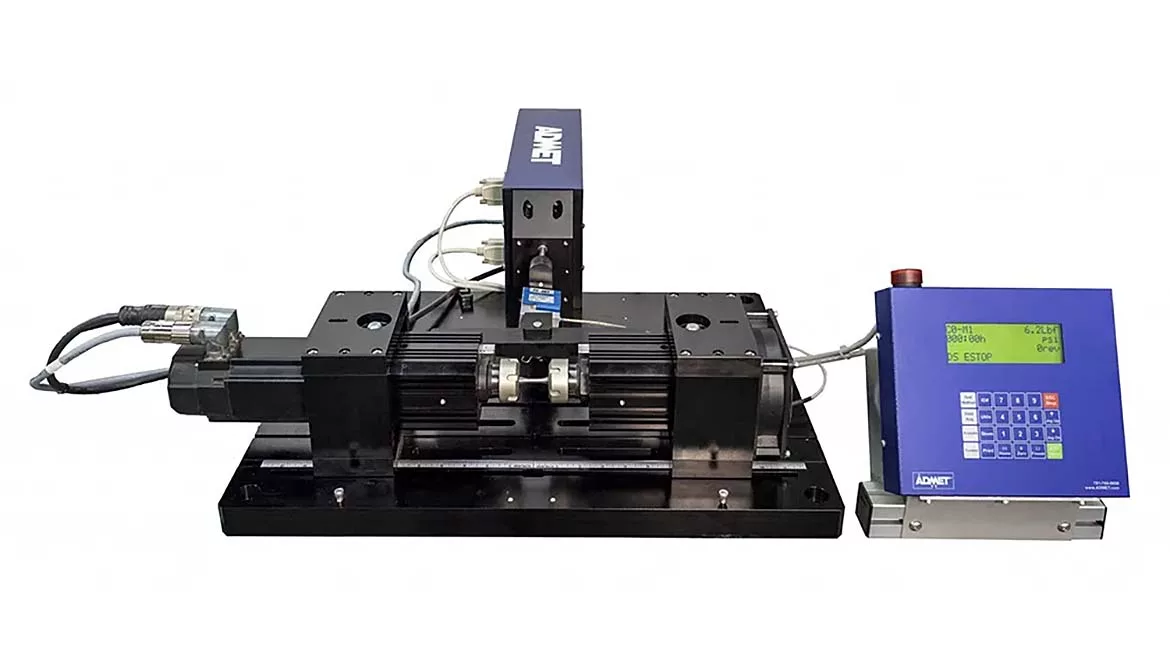
ADMET eXpert 9300 Series Rotating Beam Fatigue Testing Machine
Fatigue testing programs involving additively manufactured (AM) metal components have recently become more common as real-world applications move from simple prototyping into production of critical load-bearing parts. Studies indicate that, in certain cases, the static strength of AM metals is comparable to that of their traditional wrought or cast alternatives. In contrast, fatigue performance has emerged as the limiting factor, revealing challenges that were not apparent during earlier material screening or qualification. For quality and test engineers in industry, this shift has made measuring endurance limits one of the most consequential steps in evaluating the functional performance of AM metals.
A considerable amount of academic research has already explored fatigue behavior in additively manufactured metals, providing valuable insight into how defects, microstructure, and surface condition influence performance. This body of research has been instrumental in advancing AM technology, and our article here cannot claim to even scratch the surface on it. Instead, the goal is to shine a light on a few layers of complexity for fatigue testing real components and in true service conditions.
For these metals, fatigue performance is an emergent property of the entire process chain, not a single material property. Nevertheless, many laboratories still rely on traditional fatigue testing frameworks developed for wrought and cast metals, assuming they transfer cleanly to AM alternatives. The unique microstructural heterogeneity, defect populations, surface conditions, and anisotropy in AM parts have led to broad scatter in fatigue results, and not accounting for these factors in testing can prove quite costly, as they can drive overly conservative designs, delayed material qualification, or even unexpected failures. To ensure success, a testing approach must consider the materials science concepts at play.
How Metal 3D Printing Works and How Defects Form
In metal additive manufacturing, a printer slices a 3D model into thousands of cross-sectional layers and reconstructs them vertically, using focused thermal energy to bond the material. Whether fusing powder or depositing wire, the process completes a rapid series of microscopic welds, where the structural integrity of the entire component relies on the successful adhesion of each new layer to the one beneath it.
This layer-wise construction creates a material fundamentally different from wrought metals. As the energy source traces specific geometries, the metal experiences intense temperature spikes followed by rapid cooling. This thermal cycling generates a unique, directionally oriented grain structure and inevitably introduces microscopic inconsistencies, such as porosity or lack of fusion. Consequently, while the part may appear solid on the surface, it possesses a complex, anisotropic internal structure.
Microstructure and Anisotropy
AM parts are created via layer-wise solidification where the metal experiences rapid heating, cooling, and re-melting cycles. Many printed metal parts in the real-world are designed with complex geometries that are created through these heat cycles. As each layer is fused, a heterogenous microstructure develops which is more complex than a grain you would see in traditional metals. Instead of a uniform grain structure, you commonly get columnar grains growing in the direction of the build.
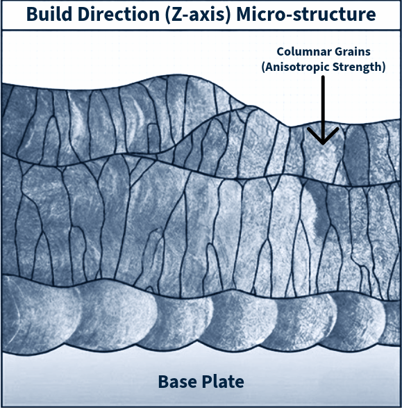
Source: ADMET
This leads to anisotropy, meaning that the mechanical properties change depending on the direction of the load relative to the build orientation. For example, a part might be incredibly strong when pulled vertically (along the Z-axis) but behave differently when loaded horizontally. Consequently, standard qualification methods that assume material uniformity can easily overlook critical weaknesses in specific orientations.
Gas Porosity and Lack of Fusion
We must also address the internal architecture. Even with optimized parameters, AM metals contain inherent defect populations. First, the “Gas Porosity” defect refers to the presence of tiny spherical bubbles trapped in the microstructure during solidification. Second, the “Lack of Fusion” defect occurs when irregular voids form in imperfectly bonded layers.
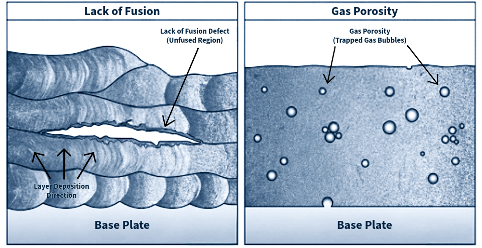
Source: ADMET
These aren’t necessarily signs of ‘bad’ manufacturing; they are often intrinsic tradeoffs of the laser-powder interaction in metal AM manufacturing. However, in a cyclic loading environment, these features act as microscopic stress raisers that compromise long-term durability. Consequently, the fatigue life of an AM part is often determined not by the strength of the metal itself, but by the size and location of its most critical defect.
Surface Condition
Finally, the surface texture is often the biggest weak point for fatigue. Because 3D printers build in layers, the outer “skin” of the part is rarely smooth; it suffers from a microscopic “stair-step” effect and is often covered in leftover grit. To an engineer, this roughness is dangerous. Every tiny valley or scratch acts as a “stress concentrator,” or a pre-made starting line for cracks to form when the part is used.
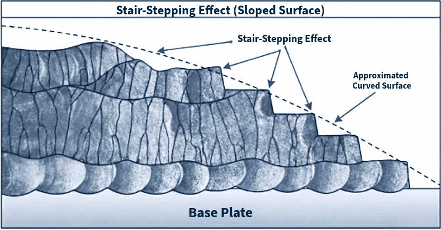
Source: ADMET
While we can smooth these surfaces using traditional machining or high-pressure heat treatments, these aren’t magic wands. Polishing works on the outside, but it often cannot reach the complex internal channels that likely justified using 3D printing in the first place. These treatments improve the part, but they are variable corrections; they cannot hit a true “undo” button on the part’s thermal history or guarantee the uniformity of traditional metal.
Why This Matters for Fatigue
From a fatigue perspective, each of these microscopic inconsistencies fundamentally alters the mechanics of failure. Classical fatigue life theory is defined by three distinct phases: crack initiation, crack propagation, and final fracture. While initiation typically consumes the majority of a wrought component’s useful lifespan, the defects explained above effectively bypass this first stage for AM materials. These defects function as immediate geometric stress raisers, concentrating cyclic loads intensely around micropores or surface valleys. Consequently, the material behaves as if the crack initiation phase is negligible, shifting the focus of analysis almost entirely toward defect tolerance and crack propagation rates. This reliance on pre-existing defect populations explains the broad scatter often observed in AM endurance results, as performance becomes statistically dependent on the probability of a specific defect coinciding with a high-stress region.
How To Ensure Reliable Results? Fatigue Testing Principles to Follow
Given the sensitivity of AM materials to defects and surface conditions, testing protocols must be rigorous. To capture a realistic picture of endurance, engineers should adhere to the following five principles:
1. Follow a standard, and follow it well
While AM is a novel technology, the fundamental physics of testing remain unchanged. Adhering to established standards such as ISO 1143 (for rotating bar bending) or ASTM E466 (for force-controlled axial amplitude) is critical. Because AM materials inherently exhibit high data scatter due to internal defects, it is vital to minimize experimental scatter. Strict adherence to alignment checks, load verification, and gripping techniques ensures that the variability in your data reflects the material quality, not the test setup.
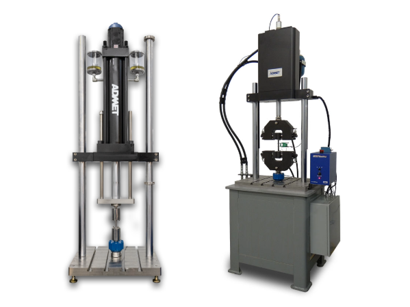
ADMET Axial Tension-Compression Fatigue Testing Machines: eXpert 5900 Series (Electromechanical) and 1900 Series (Servohydraulic). Source: ADMET
2. Test as you fly
In the aerospace industry, “test as you fly” is a common paradigm, meaning that it is critical to align test conditions as closely with the operating environment as possible. Standard fatigue coupons are often machined and polished to a mirror finish, representing the “best case” material scenario. However, this is rarely how AM parts are deployed. If your final component will be used with an “as-printed” surface, your test coupons should retain that same surface texture. Furthermore, because of anisotropy, coupons must be printed in the same build orientation (Z-axis vs. X-Y plane) as the critical features of the final part. Testing a vertically printed coupon to validate a horizontally printed load-bearing arm will yield dangerously misleading data.
3. Know how to ask “Why?”
In traditional metals, fatigue failure is often assumed to be a result of general stress accumulation. In AM, the specific cause matters immensely. Don’t just record the number of cycles to failure; perform fractography on the broken specimens. Did the crack initiate from a lack-of-fusion void? A surface particle? A gas pore?
Understanding the origin of the failure creates a feedback loop for the manufacturing team. If failures are consistently driven by internal porosity, the print parameters need adjustment; if they are driven by surface roughness, post-processing strategies must be reviewed.
4. Keep a wide S-N curve
AM fatigue data is notoriously noisy. A single batch of specimens can exhibit failures ranging from 104 to 106 cycles at the same stress level, depending on whether a defect happened to align with a high-stress region.
To account for this probabilistic nature, engineers must test a larger sample size than usual to build reliable Probability-Stress-Life (P-S-N) curves. Relying on a small sample size can result in an “optimistic” endurance limit that vanishes in real-world production.
5. Use the right equipment
Because valid S-N curves for AM require high cycle counts (often running to 107 cycles) and larger sample populations, test efficiency is paramount. Modern testing systems, such as high-frequency resonance machines, can significantly reduce the time required to generate a full curve. Furthermore, the equipment must offer high dynamic stiffness and precise alignment to prevent introducing bending moments that could skew results on brittle as-printed surfaces.
Conclusion
Additive manufacturing offers geometric freedom that was previously impossible, but it demands a higher standard of validation. The “print and pray” approach is incompatible with critical load-bearing applications. By acknowledging the roles of surface roughness, porosity, and anisotropy, and by adapting fatigue testing programs to account for these emergent properties, engineers can confidently qualify AM parts. The goal is not to eliminate every defect, which is often impossible, but to understand them well enough to design around them. Only then can AM transition from a prototyping novelty to a pillar of industrial reliability.
Looking for a reprint of this article?
From high-res PDFs to custom plaques, order your copy today!


