X-Ray and CT Automation Advances Make Aerospace Inspection Easier
How the advances are benefitting aerospace engineers with increased flexibility, improved image quality, better reporting and data storage capabilities.
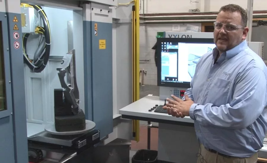
Chris Cherry, YXLON application engineer manager, performs an inspection scan with YXLON MU60 AE.
Standards and regulations rule the aerospace industry. Inspections and reviews are crucial to passenger and flight safety, but compliance with these standards can become time consuming and expensive. Advances in technology put more pressure on the inspection process. Luckily, technological advances also benefit the inspection systems, namely X-ray and computed tomography (CT) systems, by making processes faster and more cost effective.
Newer X-ray and CT inspection systems can automate many of the inspection standards that engineers must comply with during the inspection of aerospace products. A compliant system should be capable of automation for calculating and producing statistical reports, as well as for the general workload inspection. Based upon the programmed thresholds, the inspection system can alert inspectors or supervisors if too many parts fall outside of the range.
In addition, the inspection systems offer higher quality images and cut down on review and decision time for engineers…or removes manual decision making altogether by utilizing automated defect recognition (ADR). Unfortunately, we are unable to discuss ADR within the confines of this article in the depth it requires. This article will focus on how the advances in X-ray and CT automation are benefitting aerospace engineers, design engineers, mechanical engineers, operators and quality control engineers with increased flexibility, improved image quality, better reporting and data storage capabilities. All of these are helping to make their inspections easier and more effective.
Automated System Requirements Compliance
As mentioned above, the aerospace industry requires compliance with standards and regulations. This is key to the safety of the aircraft passengers. One of the main ASTM (formerly known as American Society for Testing and Materials) requirements that affect X-ray and CT inspection is DICONDE (Digital Imaging and Communications in Non-Destructive Evaluation). This standard abbreviation is in place to make all image data (including any tags such as inspector, X-ray parameters, and even geo-positioning) available and able to be displayed on imaging/analysis devices. It also includes the provisions that images be stored for reference in a viewable format.
Given that industry standards must be met and that significant amounts of time go into manually setting up and making the required calculations, some inspection systems are able to automate the process. The system integrates a default program shell for the manufacturer to define the specifications and thresholds. The system can then calculate and automatically report on the statistics. This saves the engineer time from having to do it manually in order to qualify their work.
For example, if a project requires a plate of a certain thickness, another plate with double the thickness, and multiple gages, the system can automatically take images of the plates and produce a statistical report including signal-to-noise ratios, contrast sensitivity, spatial resolution, etc.
There are controlled processes in place to verify the image quality. Some manufacturers will proof the image quality at the start of their shift and again at the end (with any other prescribed intervals also available). If the quality of both tests match, it can be reasonably assumed everything in between has the same quality.
Another controlled process example is an automated system validation. The engineer sets up the test specifications and runs the following baseline performance tests:
- Offset level evaluation: Determines whether the detector is responding within the specified range with X-rays off
- Lag test: Analyzes detector exposure and ensures that image lag (also known as ghosting) will not affect imaging performance
- Burn-in test: A longer term test to ensure the detector does not have residual image lag issues
- Spatial resolution test: The manipulator sets the prescribed geometric magnification, and the line profile is placed automatically for Duplex Wire IQI (E2002) analysis
- Contrast sensitivity test: ASTM E1025 IQI holes are evaluated; image registration is performed to detect the holes for thin and thick materials
- Signal-to-noise ratio test: Measures signal-to-noise ratio at the predefined areas in both material thicknesses of the duplex phantom
- Bad pixel report form: This report indicates the total number of pixel clusters and bad lines as well as the size and position of the indications; after entering the limits, the status is processed automatically
- System test results form: The test results form (also generated as a pdf) is defined in the ASTM E2737 and contains all measured parameters describing core image quality, material thickness range, and detector degradation.
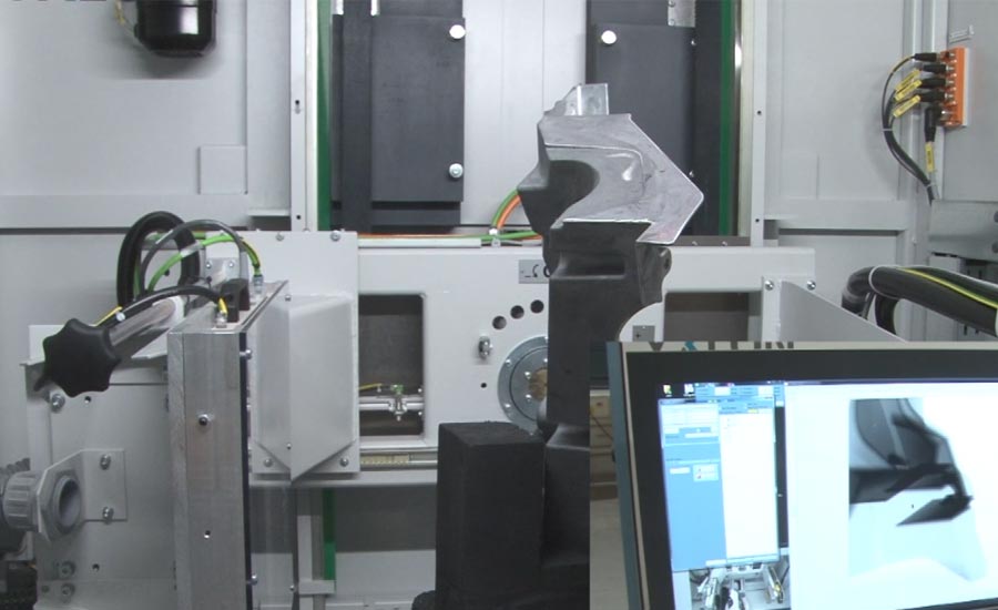
In the picture-in-picture, the operator can live view the part as it moves through a series of programmed views without operator interaction once programmed.
Flexible Programming
Advances in X-ray and CT automation systems allow for more flexible programming features. It is possible to run standard inspections, mixed program inspections, and CT inspections for 3D inspecting. The accuracy and repeatability of the imaging can equal fully robotic systems while maintaining maximum flexibility for other uses. These systems also keep statistics on the inspection failures to track issues and manufacturing trends that might not have been caught before.
The imaging process has also been updated in the way the part is positioned and the images are taken. Rather than using a robotic arm, the system automatically shifts the part, as well X-ray tube and detector positions to get the images required. In many cases, this allows for multiple part fixturing, imaging of multiple parts at one time (for small part examination), or the complete inspection of very heavy or over-sized parts. This covers most applications, but the ability to use the robotic arm is still present for specific requirements.
Brilliant image quality is essential, especially for the rigorous demands of aerospace. When it comes to safety-critical and structural cast part testing, the right tools make a big difference. A 16-bit detector with premium pixel quality and a Variofocus X-ray tube are among the most powerful tools available. Whichever detector and X-ray tube are selected, the goal is to ensure reaching the optimal values for the focal spot size, detector resolution, magnification, and required inspection speeds.
Beyond selecting the high-quality components, the operator needs to understand how they work together. Since this can require a particular level of experience and training, it is best if the system can automatically adjust to predetermined values that are recommended for the given application.
Improved Image Quality
The image acquisition parameters must be adjusted for the unique inspection task. This includes adjusting for imaging speed, radiographic contrast, and gray value ranges. It would also need an assessment of the part geometry in the image so the system can make the right decision about the part.
Since the imaging typically occurs far faster than a single operator could review, the system applies the programmed settings, takes the images at specific programmed locations, and then feeds the images to a separate machine for offline review. If desired, the engineer can instead choose to review images and positions as they are acquired. The system can also be run so it pauses at each position, as well as be run manually to provide interaction with the system (rotating, tilting, etc.) to acquire views that will be eventually programmed or to manually inspect the part.
Digital Database Advantages
Most aerospace companies require part images be stored for a specific number of years. The requirement is generally based on the lifetime of the part and can be anywhere from five to 30+ years. Most companies are transitioning to digital databases from film. Below are key disadvantages of film:
- Film cataloged and stored in warehouses degrades to the point of becoming unreadable
- Film stored in warehouses can be lost due to disasters including flood, earthquake, fire, and more
- It is more expensive and takes longer to share the data with other manufacturing sites and engineers around the world which can cause tasks to be duplicated
In addition to programming a chain of images, advanced X-ray and CT automation systems allow integration into networking. Storing the images on a network server keeps a database of all the information associated with the part:
- X-ray settings used
- Detector settings used
- Inspection and creation dates
- Pass/ Fail criteria
- Double scrutiny results
- and many more inspection criteria parameters
Another big advantage of digital networks is that systems are backed up with separate storage protocols and maintained by IT professionals. And, as mentioned earlier, DICONDE compliance ensures ease of viewing the data in the near and distant future.
Now you see how the advances in X-ray and CT automation are helping to make inspections easier for aerospace engineers, design engineers, mechanical engineers, operators and quality control engineers with increased flexibility, improved image quality, better reporting and data storage capabilities.
Looking for a reprint of this article?
From high-res PDFs to custom plaques, order your copy today!


