Several Common Image Analysis Software Tools in Machine Vision
There are many different ways that an image can be distorted.
In the world of machine vision, as in any tech field, there is a distinct divide between hardware and software. The hardware includes components of machine imaging systems such as the physical camera, lensing, cable interfaces, the PC or processor, etc. and are defined by rigid specifications (i.e. resolution of a camera, processing power, bandwidth of interface). The software side is more creative and flexible. I remember when I started my first job in this field I couldn’t believe what imaging systems were capable of and even now, some of it still feels like a magic trick. This article will briefly touch on some of the most common software analysis tools that are employed in machine vision and which serve as the foundation for more complex inspections and without which, machine vision would not be capable of everything it does.
Image perspective correction
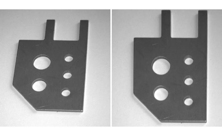
There are many different ways that an image can be distorted. One of the most common is perspective distortion. Cameras often take images at an angle from an object as opposed to looking straight onto it. As is often the case in manufacturing, physical constraints can limit possible camera placement leading to images being taken at an angle. This causes the part of the object closer to the camera to appear larger and can throw off any subsequent inspections such as measuring distances or pattern detections. This is where image correction comes into play. Using software algorithms, the image can be rearranged to look as if the camera were taking images directly above the object and this allows for more accurate inspections for basically all subsequent machine vision tools. Another example of perspective correction is when a camera takes an image of a circular object (the cylindrical side of a soup can, for example). Software is then able to “unwrap” the label and have the image appear as a flat object which allows for further imaging software (such as barcode or letter reading) to be applied.
Here is an example of a camera taking an image at a slight angle from an object due to space constraints. The image on the left is before correction and the image on the right is after correction—now ready for distance measuring and hole quality inspections.
White balancing for color cameras
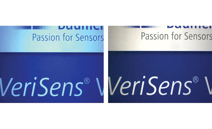
Color is a complicated concept in machine vision. As humans, our eyes and brains are truly amazing at seeing and understanding color intuitively—doing so much automatically that we take it for granted. Unfortunately, cameras and the images that they render have to be taught and corrected through software algorithms. One such correction that must be made to get true colors is called white balancing.
Unlike the human eye, which is fully capable of automatically adjusting an image under different temperatures of light, the camera must be calibrated when under different lights to get a true representation of color. This is done by placing a white or gray surface under the camera “teaching” the camera to correct for any cast that is shed by different color lights. The software then automatically adjusts the image to correct for this cast. For example, LED illumination (which is commonly used in machine vision applications) often casts a bluish hue. In this image, the left side illustrates this blue cast before any white balancing and the right side is after the correction has been made.
Sub pixel accuracy
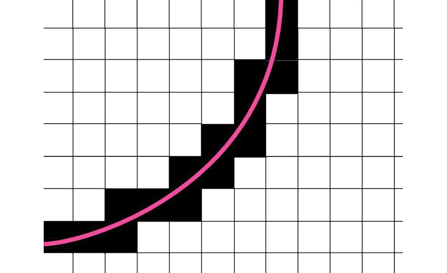
All cameras have a certain number of pixels determined by the size of the sensor that is built into the camera. This is a fixed value and cannot change—higher resolution sensors have more pixels than lower resolution sensors. However, in certain applications and instances, software can determine the edge of a shape or distance of an object within an image even more accurately than the pixels themselves (the camera’s hardware) would seem to allow. This is accomplished through algorithms that take the pixels that the image is seeing and extrapolating a more detailed line through the pixels. For example, in measuring applications, the edge of an object often covers multiple layer of pixels within an image and using algorithms, vision imaging software is able to determine where a most likely real edge is within the image—even if it means that edge is between pixels or inside of pixels. This is where the name sub-pixel accuracy comes from. Below is an image illustrating this concept. In this example, the software determines the most likely actual location of the circle edge despite it lying within the individual pixels picked up by the camera. Algorithms can do a good job of predicting this line. Here is a greatly magnified image to where the pixels are visible and the pink line is a software algorithm detecting the best fit line at the sub pixel level.
Care needs to be taken when using and relying on sub pixel accuracy. There are instances where it would not make sense. For example, take an application where we’re looking for contamination on an object. In this instance, the software would need to pick up at least one pixel of contamination on the image (i.e. a dark or light spot where there shouldn’t be any)—and preferably a multiple pixel group to ensure any noise on the sensor (dead pixels, etc.) doesn’t get counted as contamination. There is no way to accurately determine contamination without explicitly counting the pixels that are dark or light in whole numbers. There is no fractional or sub pixel contamination count and in this instance the accuracy of the application really is limited by the number of pixels within the image (i.e. the resolution of the camera). So, as with all software, it is important to understand the concepts behind the algorithms as they will help determine when they can be used.
Conclusion
The field of machine vision has been and continues to be incredibly influential in solving some of the most complex applications in the world of automation and beyond. While the hardware certainly is a wonder of its own, it really is the software and the analysis tools behind the scenes that allow these machines to do the wonderful things they are capable of. This article covered some of the most common and basic software algorithms, when to use them, and how they work. These are the building blocks for many of the most advanced and complex machine imaging software tools. This field is fascinating because it is changing daily. New algorithms and tools are continuously being discovered, developed, and improved upon to solve the most challenging problems of our day. V&S
Looking for a reprint of this article?
From high-res PDFs to custom plaques, order your copy today!


