Vision & Sensors | Lighting
Creative Illumination Techniques Enable Computational Imaging
Computational imaging can simplify certain problems that are difficult to solve with standard visual imaging.
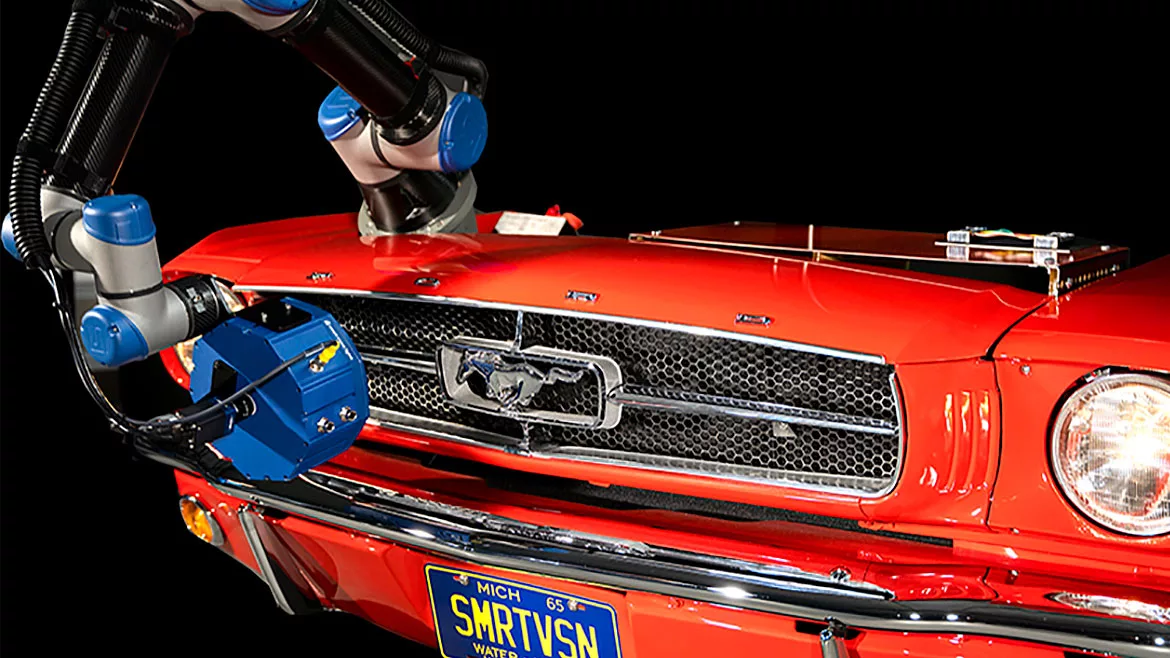
Image Source: Smart Vision Lights
The concept of computational imaging may be new to many, but the value of this already somewhat mature technology is far-reaching. Applications involving multi-image and multi-light-imaging input with computed output images based on algorithms have expanded well beyond the original realm of R&D. This technology has found its way into industrial automated inspection, where the creative use of illumination components has emerged as an enabling technology providing valuable imaging capabilities.
Broadly stated, the term “computational imaging” may be applied to varying techniques that employ algorithms to create a single image from more than a single optical acquisition. Research on computational imaging involves lens-less, single-pixel, and even flat cameras. Machine vision implementations of computational imaging are much more mature, and components and software for specific application areas easier to use than ever. In two common use cases, illumination devices and controls contribute to key imaging capabilities. These use cases are photometric stereo (or shape-from-shading) imaging, used to highlight geometric features, and high-resolution color imaging.
Illumination Supporting Photometric Stereo (Shape From Shading)
Photometric stereo imaging is closely related to 3D imaging. While not a direct physical 3D representation of a scene, a photometric stereo image represents the geometric shape of features in the image, and the imaging is much more easily implemented. Typically, a single camera is used and multiple illumination sources over multiple images are combined in software that is readily available from and supported by many machine vision components and software libraries.
Photometric Stereo Overview
Fundamentally, photometric stereo in computational imaging for machine vision leverages multi-angle illumination to extract features whose height varies from that of surrounding surfaces. In a single-image acquisition, the features appear bright with respect to the nearby surface. This lighting technique is widely used in machine vision to effectively detect surface features and defects. However, when a series of images is acquired with illumination coming from different angles (Figure 1), the resulting images can be combined using a shape-from-shading algorithm to obtain an uncalibrated 3D image representation of the relative height of features.
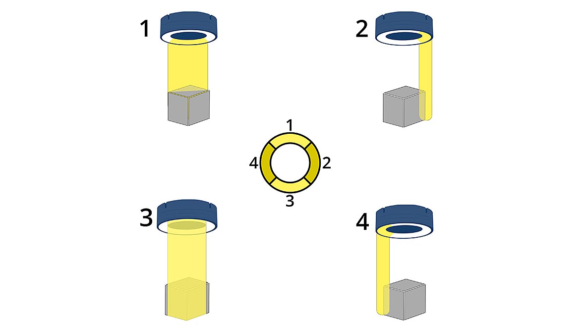
Figure 1: Photometric stereo in computational imaging for machine vision leverages multi-angle illumination to extract features whose height varies from that of surrounding surfaces. | Image Source: Smart Vision Lights
Unlike more complex 3D imaging systems, the resulting photometric stereo image is often a curvature image, not a pure height or depth image. The image data create a grayscale representation of the surface geometry of discrete features with localized height variation. Those that are farther away in height or depth from surrounding surfaces will have a higher grayscale pixel value. In addition to processing curvature images, advanced vision libraries can process directional images though other algorithms (Figure 2). Filters include texture, mean, local shape, local contrast, Gaussian, and albedo. Each filter highlights different surface properties, and users can choose the one that is best for their particular application.
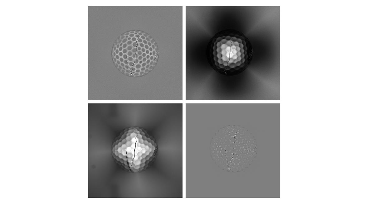
Figure 2: The output of photometric stereo imaging varies depending on the choice of processing algorithm. The same directional input data is shown using Matrox Design Assistant’s mean curvature (top left), local contrast (top right), texture (bottom left), and Gaussian curvature (bottom right) algorithms. Additional algorithms include albedo and local shape. The right choice depends on the object being imaged and the type of feature being detected. | Image Source: Smart Vision Lights
The broad use for photometric stereo imaging is to highlight features in an image where the object or scene lacks grayscale content but individual features have geometric variation relative to the surface. One example is the imaging of tires for identification based on sidewall graphics and characters. With information provided by multi-image representation, the grayscale image can be processed using typical machine vision tools to perform inspection tasks such as defect detection, OCR/OCV, and measurement. Surfaces with embossed or debossed codes or characters also are good candidates for photometric stereo imaging. Similarly, many products and components with low-contrast features but geometric structure can benefit from this imaging technique (Figure 3).
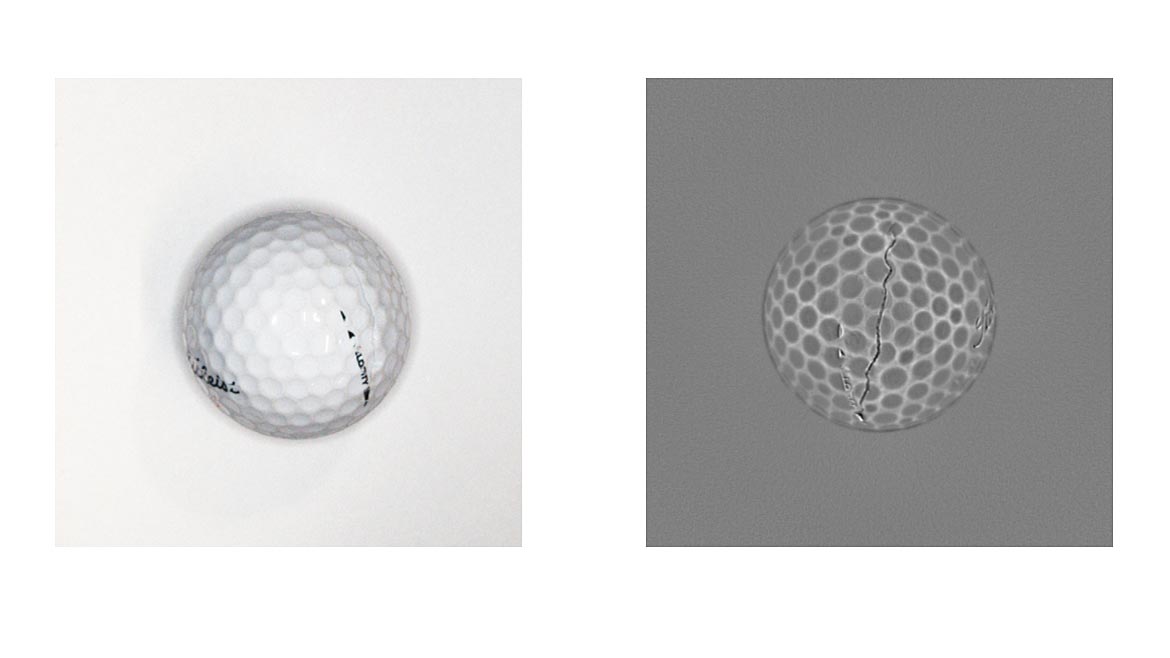
Figure 3: Side-by-side comparison of a golf ball inspection using a standard color image (left) and a photometric stereo image (right). A crack that is barely detectable amid the surface texture gloss and specular highlights of the visual image is easily detectable in photometric stereo. The computed surface in the photometric stereo image removes visual noise that makes the color image difficult but retains surface details that are important for inspection | Image Source: Smart Vision Lights
Implementation Of Illumination For Photometric Stereo Imaging
Photometric stereo imaging relies heavily on software and algorithms that are used to combine and process varying views of an object. Implementation of this multi-image computational technique starts with illumination components. Typically, with a single camera generally centered over an object, four separate images are acquired. Each has illumination at a different clocking angle around the field of view — most often at 0, 90, 180, and 270 degrees (or more informally stated, on the four sides of the camera’s rectangular or square field of view). The illumination angle of each light defines the features that will be highlighted.
Illumination components are selected based on the required field of view, and different applications might use multiple individual lights or just a single light source with multiple controllable illumination angles — for example, a ring light with multiple individually controlled segments or zones (Figure 4). For each image acquired, a different light (or lighting zone) is used. The sequencing for the multi-image acquisition is easily implemented using a lighting controller that interfaces with the lights, the camera, and the acquisition software.
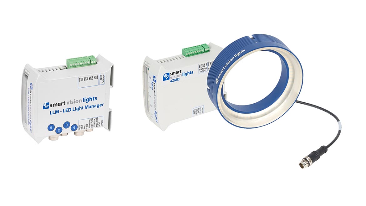
Figure 4: An LED programmable sequence controller (left) and a multi-zone light kit (right). These plug-and-play solutions are easy to implement, work with common hardware and software, and make computational imaging accessible to all levels of users. | Image Source: Smart Vision Lights
High-Resolution Color Images With Grayscale Cameras And Computational Imaging
Another example of illumination combined with computational imaging involves the acquisition of high-resolution color images. In a single-sensor camera, color images are produced by fabricating a red, green, or blue broad bandpass filter over each individual pixel. In most RGB imaging, this technique is called Bayer filtering because of the layout of the filters on the pixels. With each pixel having only one of three colors, the final full-color image must be reconstructed from adjacent pixels in a process called de-Bayering (or de-mosaicking). Due to this pixel combination, the effective spatial resolution of the resulting image is significantly reduced compared to the actual resolution of the sensor. An effective and simple solution to the loss of resolution is the implementation of computational imaging with multispectral illumination.
Executing Color Imaging With A Grayscale Camera
A lighting component that can illuminate the field of view with multiple colors (or multispectral) can mimic the broad band filtering used on a color camera on a grayscale camera that does not have pixel-level filters. In this implementation of computational imaging, the multiple images acquired are linked to illumination of a part using three broad wavelength colors: red, green, and blue. As with photometric stereo, an appropriate lighting controller can be used to further simplify the acquisition. The resulting images contain full-resolution representations of the red, green, and blue content of the scene. In software, the three images are easily combined into a multi-channel color image with a structure as required by the specific application (Figure 5).
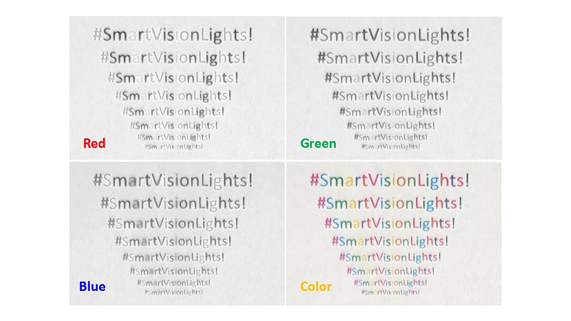
Figure 5: Three images captured by a monochrome camera, each strobed with red, green, or blue light are combined into a full color image, which preserves resolution when compared to a Bayer color image that loses resolution in the color interpolation process. | Image Source: Smart Vision Lights
In some cases, not only the spatial resolution but also the color fidelity might be improved over simple Bayer filtering. The consistency of the illumination source can introduce a level of reliability and color reproduction that could exceed the capability of on-sensor filtering in some applications. This computational imaging technique gives users the benefits of color imaging without the loss of resolution associated with Bayer color cameras and on-chip color filters.
Parts In Motion
Not just for stationary parts or objects, computational imaging can be easily used in applications where parts (or even imaging components) are in motion. The technique involves careful specification and in some cases additional processing. As with all imaging applications involving moving parts, to minimize motion blur, key metrics to consider are the speed of motion and the exposure (or strobe) duration of each image. In photometric stereo imaging, one must also consider the rate of multi-image acquisition and the amount of movement of the part in the field of view over the aggregate acquisition time.
If the part is moving slowly enough and the imaging rate is high enough, the multiple images obtained might be sufficiently close to each other in terms of part movement to provide a suitable combined image. Fueled by the rise of low-cost, high-speed CMOS imagers, this process is easier than ever. If intra-scene movement is too great, simply use a faster CMOS camera.
If the part moves too much from image to image and a faster camera isn’t an option, it might be necessary to preprocess images to digitally align them. This involves comparing suitable features on each image to the first image taken and then applying appropriate translations to match those features for the subsequent multi-image computation (Figure 6).
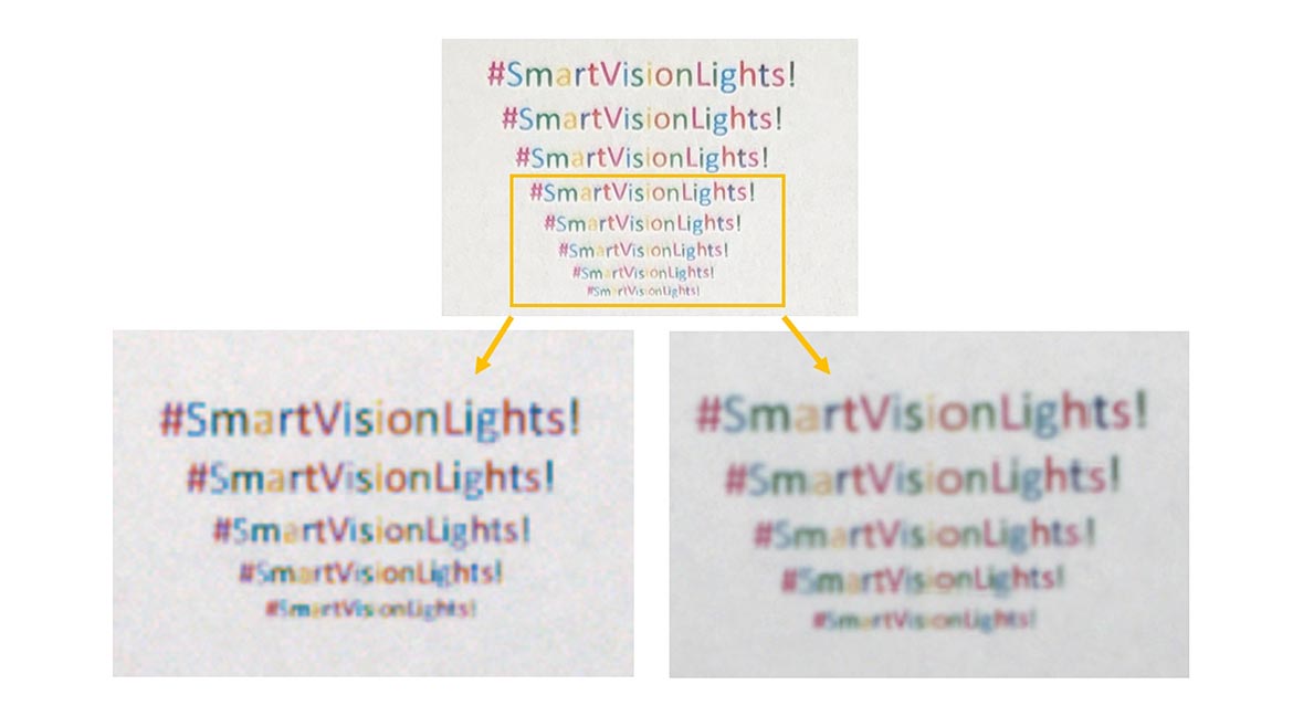
Figure 6: Zooming in on the last few lines of the colored text reveals the color camera’s resolution degradation at the pixel level with lost definition and color checkering. Computational imaging color remains true, resolution remains stable, and background uniformity results from the monochrome camera’s greater sensitivity and lower noise. | Image Source: Smart Vision Lights
Software tools can realign an object down to the pixel across multiple captured frames and even correct rotational variation. Standard tools in most machine vision libraries can correct motion to make these computational imaging techniques useful, even if a part isn’t still or registered as the sequence is gathered.
Another technique is to externally track the motion of a part between each image (for example, on a conveyor) and then directly apply a transformation based on the known amount of physical offset of the images. In all cases, of course, it is mandatory that during the acquisition of images, the part remains in the camera’s field of view. This method is particularly well suited for objects moving on an encoded conveyor belt and images captured with line scan cameras.
Though it may seem a more complex solution, computational imaging can actually simplify certain problems that are difficult to solve with standard visual imaging. Computational imaging, particularly as enabled by today’s lighting components and controllers, has become an easy-to-implement and valuable imaging technique that is readily accessible for a wide range of machine vision applications.
Looking for a reprint of this article?
From high-res PDFs to custom plaques, order your copy today!


