Vision & Sensors | Measurement
Tips on Making Precision Measurements with Machine Vision – Part 3
Here we’ll look at characteristics and components of the vision system that can limit the achievable accuracy.
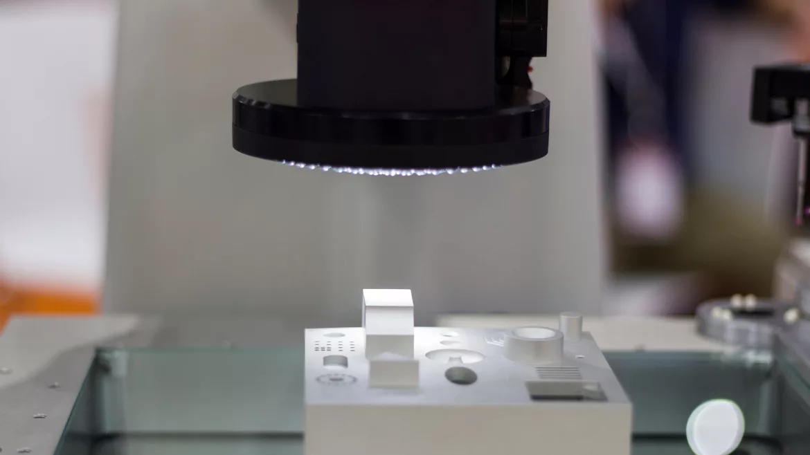
Image Source: Warut1 / iStock / Getty Images
The first part of this series covered the basic principles that make high-accuracy measurements possible for machine vision. The second part of the series looked at challenges to accurate measurements due to the application conditions. This third part looks at characteristics and components of the vision system that can limit the achievable accuracy.

Defective Pixels
It’s not widely known, but image sensors have defective pixels sometimes called blemishes. Defective pixels may be single pixels, small clusters of pixels, or lines, typically columns of pixels. (See Figure 1.) Each image sensor manufacturer determines the number of allowable defective pixels. This information is usually available only under a confidentiality agreement. It might be possible to pay extra for the camera and get a higher-grade sensor with fewer defective pixels.
Cameras tend to mask detective pixels. The camera typically contains a table or map of the specific defective pixels for its image sensor. Camera circuitry uses this map to substitute a value for the defective pixel. The substitute value may be the average of good pixels around the defective pixel, or it may be a hold onto the value from the last good pixel during readout.
In making measurements, defective pixels very near a point of measurement give a value that can lead to an outlier data point. If this proves serious, some cameras make the defective pixel map/list available to software. Check camera specifications carefully before making a selection. You may need to create an algorithm to use the map and eliminate possibly bad data before calculating the measurement.

Telecentric Lenses
Telecentric lenses (see Figure 2) have gained favor in metrology applications because they mostly avoid parallax errors, have low distortion, and change magnification very little over their depth-of-field. To achieve these benefits, telecentric lenses are limited to smaller apertures (larger f-numbers). The smaller apertures limit the telecentric lens’ optical resolution. Still, when avoiding perspective distortion is necessary telecentric lenses are very useful.There is a belief that telecentric lenses do not have distortion. This is not true. Telecentric lenses have low distortion compared to most conventional lenses. Even the telecentric lens’ low distortion is significant enough to produce errors in high-precision measurements unless calibration corrects for the distortion. Typically, telecentric lenses have wave distortion. Some software packages do better at compensating for wave distortion than others.
Since telecentric lenses must be bigger than the field-of-view, they are very convenient for measuring small parts. As the part size grows and the field-of-view gets larger, the lens gets larger, longer, heavier, and more expensive.
Color
There are two aspects of color or spectrum with regard to measurements. One aspect addresses the performance of lenses and interference from ambient light. The other aspect addresses the uncommon need for color imaging when accurate measurements are also needed.
Addressing first the desired spectrum of light, when color imaging is not needed, the best choice of light will be a narrow band light source such as that from colored LEDs along with a matching bandpass filter over the camera lens. This will minimize any concern over a lens’ chromatic aberration that compromises image quality. It also suppresses the effects of ambient light. Ambient light is noise that can only reduce contrast and lead to unwanted variations from image to image. What color of light is used is mostly dependent on what color creates the highest contrast in the image and how the wavelength affects the performance (resolution) of the lens.

Making measurements from color images is more problematic; not because of image processing, but because of the way image data is sensed. Most machine vision applications use a single-chip color camera that has color filters over the pixels in a Bayer pattern as shown in Figure 3.
In the single-chip camera, every pixel delivers three values – one each for red, green, and blue. However, two values are interpolated from neighboring pixels and not sensed. The effective density of sensed light is one-quarter the number of pixels – half the number of rows and half the number of columns.
Envision the single-chip sensor as having composite pixels – a 2x2 group composed of one red, one blue, and two green pixels. The challenge for measurement is that the different colors in the composite pixel are not sensed at the same physical location. This can lead to a one pixel shift in sensed data among the three colors.
One way to deal with the spatial differences in the three colors is to treat the incoming image, not as having pixels with three values, but as three separate images – one for each color. Each of the color images is calibrated separately. The calibrated image data can be combined into a single color image if desired. This approach has the advantage of also correcting for a lens’ lateral chromatic aberration.

Another color imaging approach is to use a three-chip color camera. (See Figure 4.) In this device, the three colors are almost perfectly aligned – typically to better than one-tenth of a pixel. Calibrating each color separately can mitigate any spatial differences in the positioning of the three sensors.
The three-chip approach has, in addition to much higher cost, the disadvantage of needing special lenses due to the optical effects and the space required for the color separation prism. There may not be a suitable lens available for the application.
Bi-telecentric lenses may be used with appropriate spacers for thee-chip color cameras. There is little to no industry experience using three-chip color cameras with telecentric lenses to make accurate measurements.
Edge Angle
In the 1980’s I discovered the angle of a straight edge in the image affected the precision of its measurement. I never published those findings. Almost simultaneously, Bill Silver at Cognex wrote an also unpublished paper showing the same results.

A binary image can have as much as one-half pixel possible random error (see Figure 5). This becomes part of the precision. Gray-scale images where interpolation across the edge profile is used, have one to two orders of magnitude less error due to the pixel sampling.
What does this mean for your measurements? For straight edges, it tells you to avoid the common engineering approach of having the straight edge parallel to a row or column of pixels. Angle the camera around 7 to 10 degrees from the edge direction. If the part is free to rotate within the field-of-view or is significantly curved, then this characteristic will not help as no camera angle is better than any other.

Assumption of Perfect Pixel Spacing on Sensor
Sub-pixel measurement techniques are based on one key model or assumption: sensing elements on the image sensor are precisely positioned in the array with no optical deviation from a precision array.
High-precision measurements of image sensors, early in machine vision’s history using optical measurements, suggested there was about a 0.1-pixel variation in the pixels’ actual optical positions from the expected repetitive pixel spacing (see Figure 6).
Similar to the optical earlier observed pixel center variation is the intra-pixel sensitivity variation (IPS). The sensitivity to light of a single pixel’s photodiode varies across the photodiode. IPS can vary from pixel to pixel. IPS is very important to astronomers who image extremely distant, small, and dim objects repeatedly. Image sensors for astronomy are sometimes characterized for IPS. IPS may explain the early observed pixel center variation.
At present, there is no machine vision technique to measure or compensate for any optical pixel array distortion in machine vision. A conservative approach is to operate with the assumption there is still a 0.1-pixel distortion in the optical positions of pixels in the imaging array until data to the contrary is available.
Effective Distortion Caused by Chief Rays on the Image Side

Modern CMOS image sensors, known as front-side illuminated sensors (FSI), have walls of insulation and conductors that rise above the photosensitive area of the pixels. These walls create a “tunnel” through which the light must pass to be sensed. The geometric result of these tunnels is an apparent optical shift of the location of the pixel outward as the image moves away from the center. (See Figure 7 and Figure 8.) This results in a slight pincushion distortion of the pixels’ location.

Most CMOS image sensors use microlenses to help increase the effective fill factor of the pixels, and the microlenses tend to exacerbate the virtual distortion of the pixels’ locations.

Back-side illuminated (BSI) image sensors eliminate much of the “tunnel” but often still use microlenses. BSI sensors will have less optical distortion than FSI image sensors. Still, the microlenses will give some distortion if the angles of the chief rays on the image side are large.
The use of longer focal length lenses reduces the angle for light reaching pixels away from the center of the image and mitigates the effect of the “tunnel.” The use of a bi-telecentric lens, where the chief rays on the image side are parallel (see Figure 9) eliminates the optical pixel distortion.
Frequency Response (MTF) of Lens and Image Sensor

You may be familiar with the modulation transfer function (MTF) of a lens (Figure 10). Did you know an image sensor also has an MTF (Figure 11)? The response of an imaging system is the combination (product) of the two MTFs (Figure 12).

In measurement applications, the effect of the image sensor’s MTF, assuming a theoretically impossible lens MTF that is always 1, would have an edge with a single step somewhere in the transition between dark and light. (See Figure 13.) The position of the step would depend on the exact location of the edge.

The problem with a step in the edge slope is algorithms to determine the peak in the derivative or zero crossing in the second derivative don’t work. The result would be no sub-pixel precision capability. Under this condition, a gray-scale image measurement yields the same uncertainty as a binary image measurement.


If the measurement were to be the spacing of a series of parallel wires, the vision system would resolve each wire. However, the uncertainty of each edge of every wire would be significant. The calculated spacings would exhibit variations on the order of a pixel or two due to the aliasing caused by the image sensor.
For best results, the lens MTF should reasonably match the image sensor’s MTF, as shown in Figure 12, where the lens’ MTF is very low in the region where the image sensor is aliasing. This will give an edge with a smooth slope (Figure 14) that works very well with algorithms in machine vision software.
Conclusion
This third part in the three-part series covered challenges presented by components of the vision system. Most of these challenges are managed with good vision system design.
Together with the first two parts of the article that covered basic principles and application considerations, the shows the ability to design very high-accuracy vision systems is practical.
Looking for a reprint of this article?
From high-res PDFs to custom plaques, order your copy today!


