Lighting
Lighting Design for Machine Vision, Part 3
This article shows how the characteristics captured on the scene analysis form map into the lighting cube.

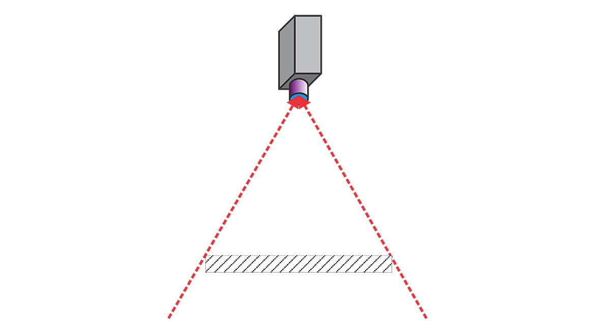
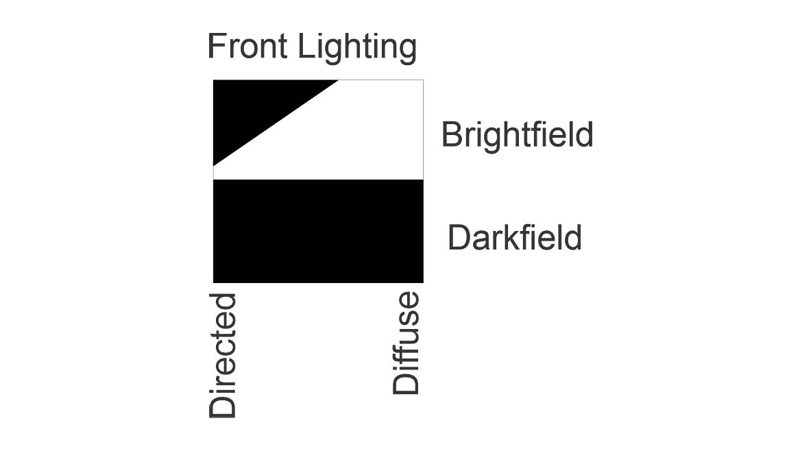
Figure 1 -- Illumination "W" for Front Lighting
This is the third article in the five-article series on lighting design for machine vision. The first article in the series introduced the scene analysis form which is a tool to determine what characteristics of a feature and its background have the potential to create contrast. The second article in the series introduced the lighting cube and showed how machine vision light sources mapped onto it. This third article shows how the characteristics captured on the scene analysis form map into the lighting cube.
This part does not include a discussion of materials that emit light since that is ordinarily not an issue addressed by engineered lighting for machine vision. Color, an extremely important property for both reflected and transmitted light and captured on the scene analysis form, is covered in the fifth article in this series.
Physical and Optical Properties
The second article in this series covered the illumination “W” for front lighting (Figure 1) and the illumination “V” for back lighting (Figure 2). The mapping of objects onto the lighting cube depends on the illumination “W” or “V”. The physical or shape properties and the optical properties of reflection and transmission of the feature or background affect the shape of the “W” and “V”.
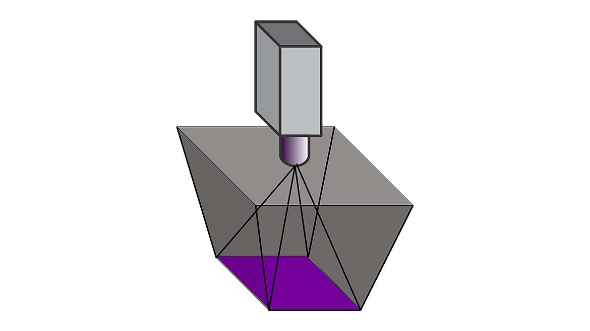
While we talk about the “W” as a two-dimensional visualization technique, it is actually a 3-dimensional concept as shown in Figure 3. This also applies to the illumination “V”. While the commonly used two-dimensional “W” and “V” will continue to be used in this article, in your lighting design, be aware that the lighting envelope is really 3-dimensional. When the surface is flat, specular, and perpendicular to the camera’s view, the “W” is exactly as shown in Figure 1.
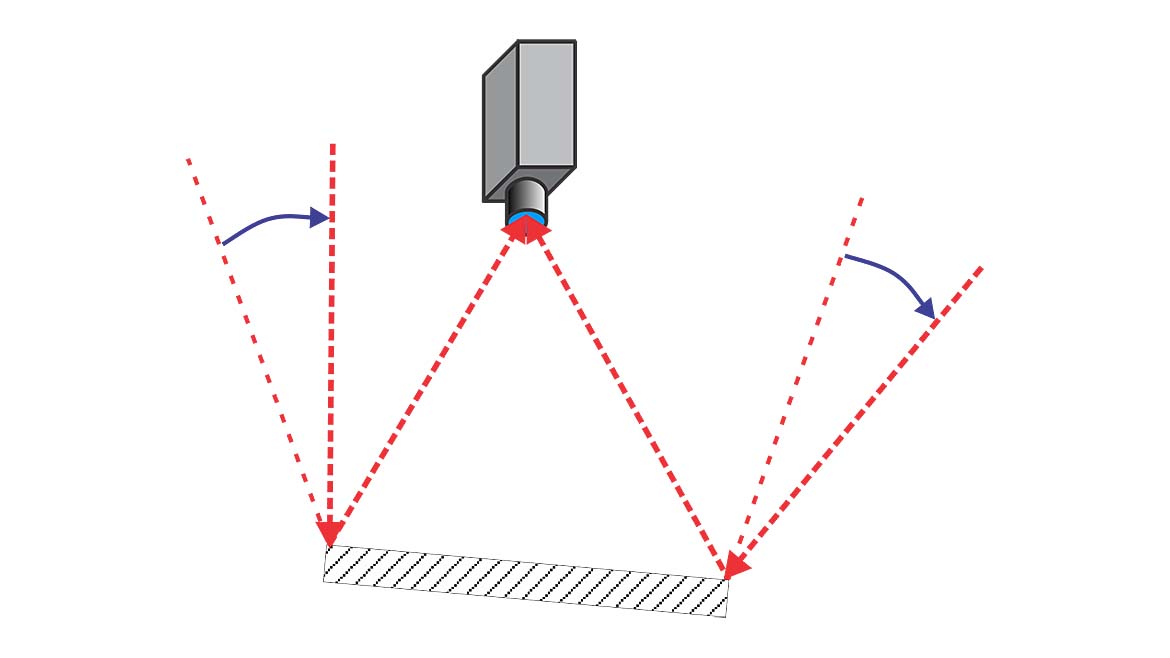
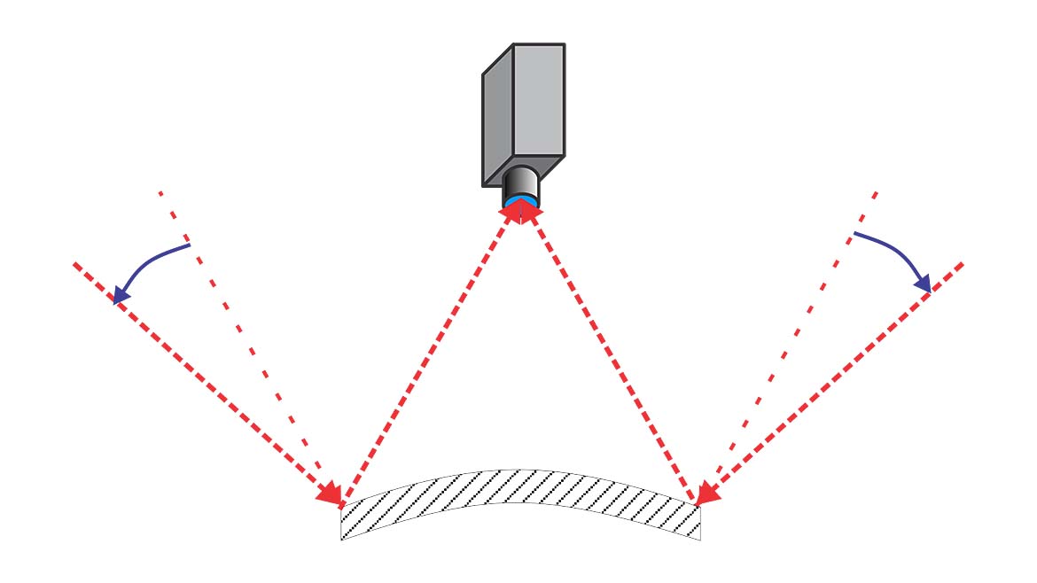
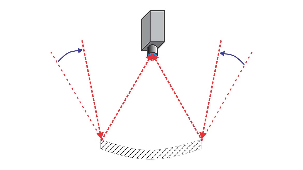
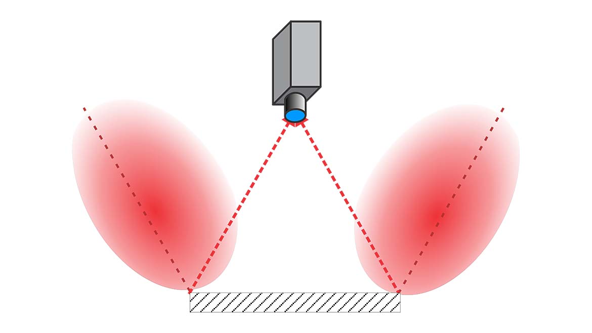
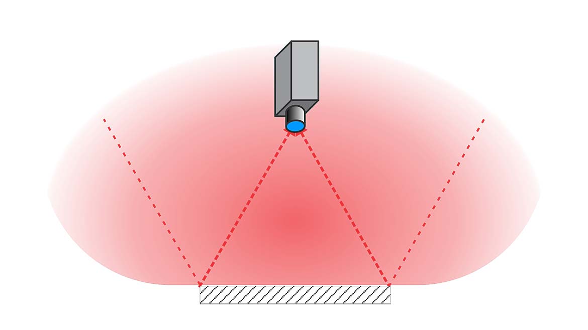
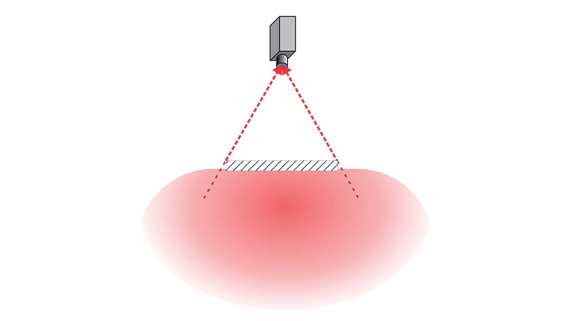
Any change in the physical properties, such as slope, tilt, or curvature, alters the “W” as shown in Figures 4 through 6.
Any change in the reflection properties from specular, blurs the outer arms of the “W”. Diffuse reflectance blurs the arms over a range of 180°. The illumination “W” virtually disappears as shown in Figure 7. Light energy striking any point on the surface from any direction is scattered, with some of the light going into the camera’s lens.
While Figure 7 seems to indicate the light is coming from the camera, the property of light called isotropy where the behavior of light is the same regardless of its direction (of incidence) applies, and Figure 7 is a reasonable representation of what happens to the illumination “W”. Semi-diffuse surfaces blur the arms of the “W” over a smaller range of angles as shown in Figure 8.
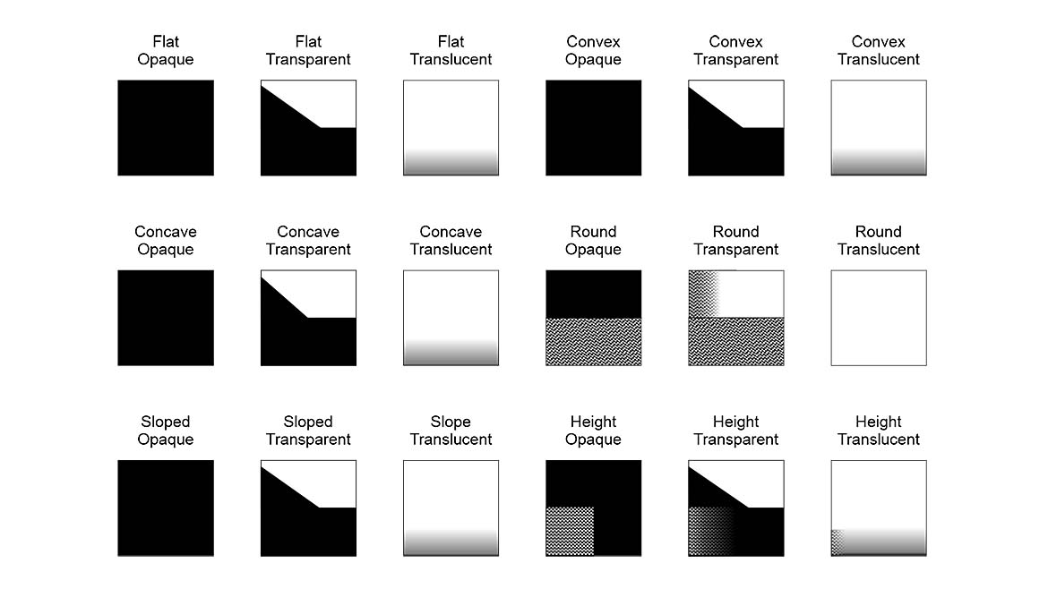
For flat transparent materials, the illumination “V” is shown in Figure 2. What Figure 2 doesn’t represent is the effects of refraction, the bending of light, when passing through the material. For surfaces that are flat, perpendicular to the camera’s view, and not excessively thick, the illumination “V” is close enough to accurate for lighting design purposes.
When the surface is curved, domed, or very thick, the illumination “V” is modified, possibly significantly, and the changes must be considered. These effects can be evaluated with ray tracing or with experimentation to predict how the illumination “V” is modified.
Translucent materials affect the illumination “V” in a manner similar to diffusely reflecting surfaces. As shown in Figure 9, incident light is scattered in all directions, effectively eliminating the illumination “V”.
Mapping Onto the Lighting Cube
Each optical property, specular, diffuse, and semi-diffuse for reflection and opaque, transparent, and translucent for transmission, is mapped with a physical property onto the lighting cube to show what lighting direction characteristics will produce a bright area and which will produce a dark area. This results in a very large number of mappings.
Like the mapping of light sources onto the lighting cube in the second article in this series, the mapping of scene characteristics onto the lighting cube is also subjective. Still, as will be shown in the fourth article, combining the mappings of scene characteristics with the mappings of light sources gives a good indication of which light source will work for most machine vision applications.
What follows is a discussion of several mappings from the scene analysis form onto the lighting cube. A full set of mappings is available for download. A link to the download is provided later in this article.
The first observation is that physical characteristics are mapped along with reflection or transmission characteristics. Reflection characteristics apply only to front lighting, and only the portion for front lighting is mapped. Transmission characteristics apply only to back lighting, and only the part of the lighting cube for back lighting is mapped.
With one exception, surfaces that transmit light also reflect light. So, your lighting design must consider both reflection (front lighting) and transmission (back lighting) into consideration. The one exception is a transparent object that is a hole – transparent by its absence. A hole will have no reflection properties.
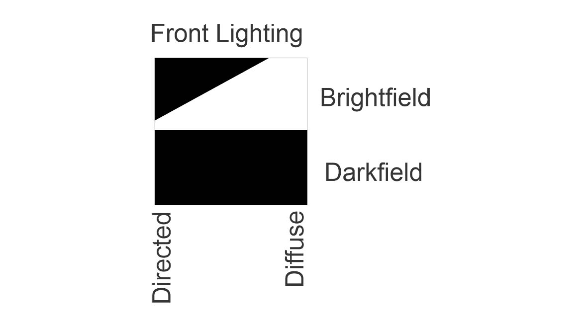
Figure 10 shows the mapping of the flat specular surface onto the lighting cube. Note for specular reflection, this mapping only applies to front lighting.
To make a specular surface bright, the whole interior of the illumination “W” needs to have light energy falling on the surface. Only a diffuse light source will make the entire surface bright. Partial bright field lighting, where the light is more directed and fills only part of the “W”, only makes a portion of the surface bright and is not usually useful for a specular surface. This is indicated by the dark triangle in the area of directed light.
A convex specular surface is similar to the flat specular surface. Since the outer legs of the illumination “W” are broader, the light source needs to be even more diffuse than for a specular surface. This is shown in Figure 11. For a concave specular surface, the “W” becomes narrower, and the light source, while still needing to be diffuse, can be less diffuse. This is shown in Figure 12.
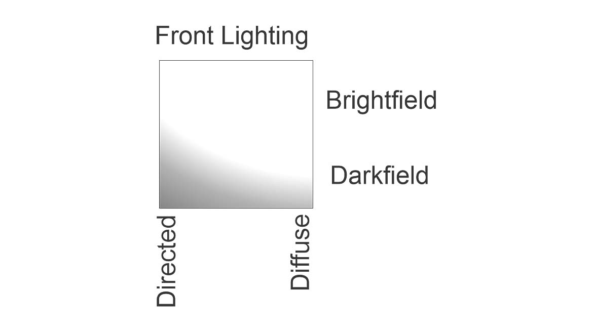
When the surface changes from specular to highly diffuse, the illumination “W” virtually disappears, as shown above in Figure 8. Light energy striking any point on the surface from any direction is scattered, with some of the light going into the camera’s lens. Mapping a flat diffuse surface onto the lighting cube shows that light from almost any angle will make the surface bright to the camera. (See Figure 13.) Extremely shallow dark field lighting will reflect less light into the lens, and the lighting cube is slightly gray.
For very diffuse surfaces, the surface shape has little effect on the light reflected into the camera except where the shape obscures some of the light from reaching the surface of a part. An example of this obscuration would be a convex, very diffuse surface illuminated from one side, with the opposite side receiving no light.
Semi-diffuse surfaces are between specular and highly diffuse surfaces. Reflected light is spread over a limited range of angles, blurring the illumination “W”. (See Figure 8.) Semi-diffuse surfaces can exhibit some glare from lighting without reflecting light as a mirror does. The flat semi-diffuse surface maps onto the lighting cube as shown in Figure 14. Since there are varying degrees of semi-diffuseness, a single mapping onto the lighting cube is only a subjective approximation.
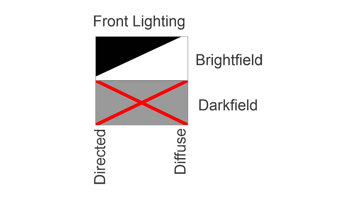
Round objects present very interesting lighting challenges for machine vision. For the purpose of mapping onto the lighting cube, a round object is any surface with sufficient curvature that the outer arms of the illumination “W” reach or exceed the horizontal.
One characteristic important to lighting design is the absence of a region for dark field illumination for front lighting. This is shown in Figure 15, where the dark field portion is X’d out.
Another interesting object to map onto the lighting cube is a curved transparent material. Obviously, this has transmissive properties for which back lighting is appropriate. However, transparent surfaces also reflect light specularly and may be considered for front lighting.
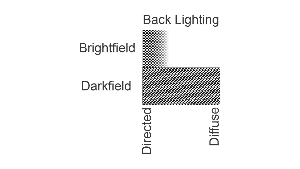
Figure 16 shows the mapping for the round transparent object for back lighting. It is different because of how light interacts with the object. Since light can refract and reflect internally, diffuse bright field back lighting will make the object bright. But more directed bright field back lighting will cause the edges to be dark. This is shown in the checkered area for directed bright field illumination. For dark field back lighting, it is possible, and even likely, that some of the object will be dark while specular reflection off the sides of the object will be seen in the camera’s image. This is shown in the hatched area in Figure 16.
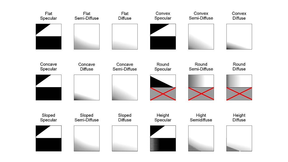
There are quite a number of mappings of scene analysis conditions onto the lighting cube. These are shown in Figure 17 for front lighting and in Figure 18 for back lighting.
You can download all the mappings at: https://drive.google.com/drive/folders/11WdHzAfFHBUO9tI7Q6zB9op8xRcPrFSb?usp=drive_link.
Conclusion
This article shows how information from the scene analysis form maps onto the lighting cube. It gives mappings based on both shape and either reflective or transmissive optical properties. The next article in this series shows how to combine the mappings from the scene analysis form with the mappings for light sources to identify a good candidate lighting approach.
Looking for a reprint of this article?
From high-res PDFs to custom plaques, order your copy today!


")


