Lighting
Lighting Design for Machine Vision, Part 4
This article provides examples of how the mappings in the previous two articles are used to identify good candidate lighting solutions.

This is the fourth article of a five-article series on lighting design for machine vision. The first article in the series introduced the scene analysis form that is an aid to determining what characteristics of a feature and its background have the potential to create contrast. The second article in the series introduced the lighting cube and showed how machine vision light sources mapped onto it. The third article in the series described the mappings of the information from the scene analysis form onto the lighting cube. This article provides examples of how the mappings in the previous two articles are used to identify good candidate lighting solutions.
Using the Mappings
Example 1
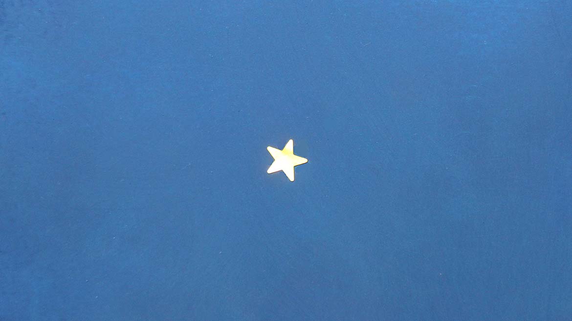
Image Source: Perry West
Let’s take a simple example — a gold star on a blue background shown in Figure 1. The scene analysis form is shown in Figure 2. The differentiating characteristics that can create contrast are circled in green.
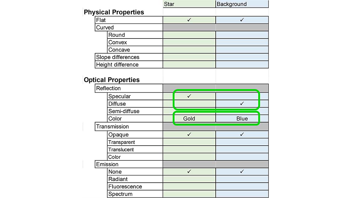
Image Source: Perry West
Setting aside color, which is very significant in creating contrast and is covered in the fifth article in this series, we have two different conditions: flat and specular, and flat and diffuse. Take the mappings of each and compute the absolute difference using a graphics program such as Photoshop, MatLab, or your machine vision software library. The result is shown in Figure 3.
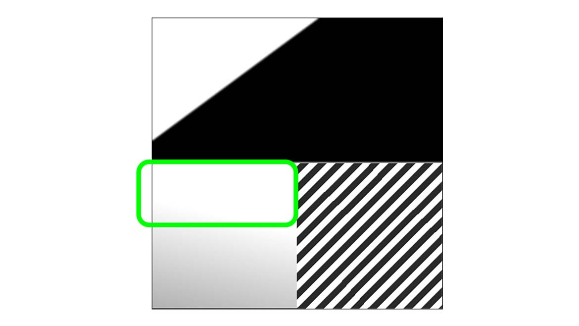
Image Source: Perry West
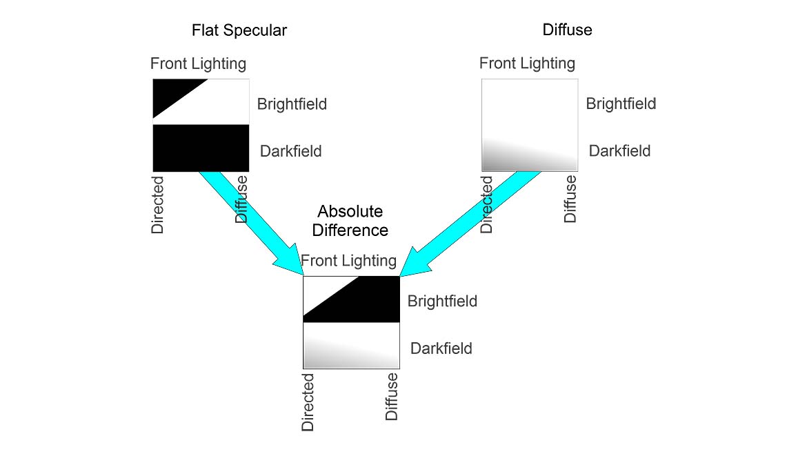
Image Source: Perry West
You will notice that the difference mapping has light and dark areas. The lighter areas indicate the lighting that produces higher contrast. Darker areas indicate lighting that produces little or no contrast. While the lower right-hand corner seems to be the best area for good contrast, remember that this corner is invalid — there is no highly diffuse back lighting method. This is indicated by the added hatched area in Figure 4.
The area of best contrast appears to be high-angle dark field illumination, as shown by the green rectangle in Figure 4.
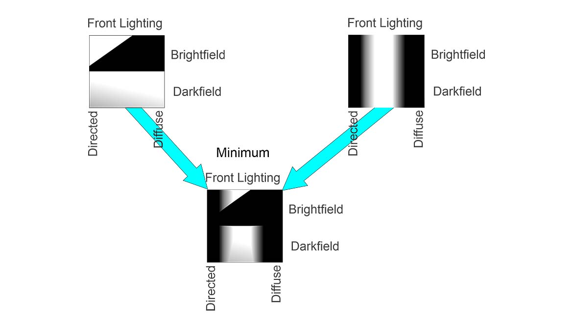
Image Source: Perry West
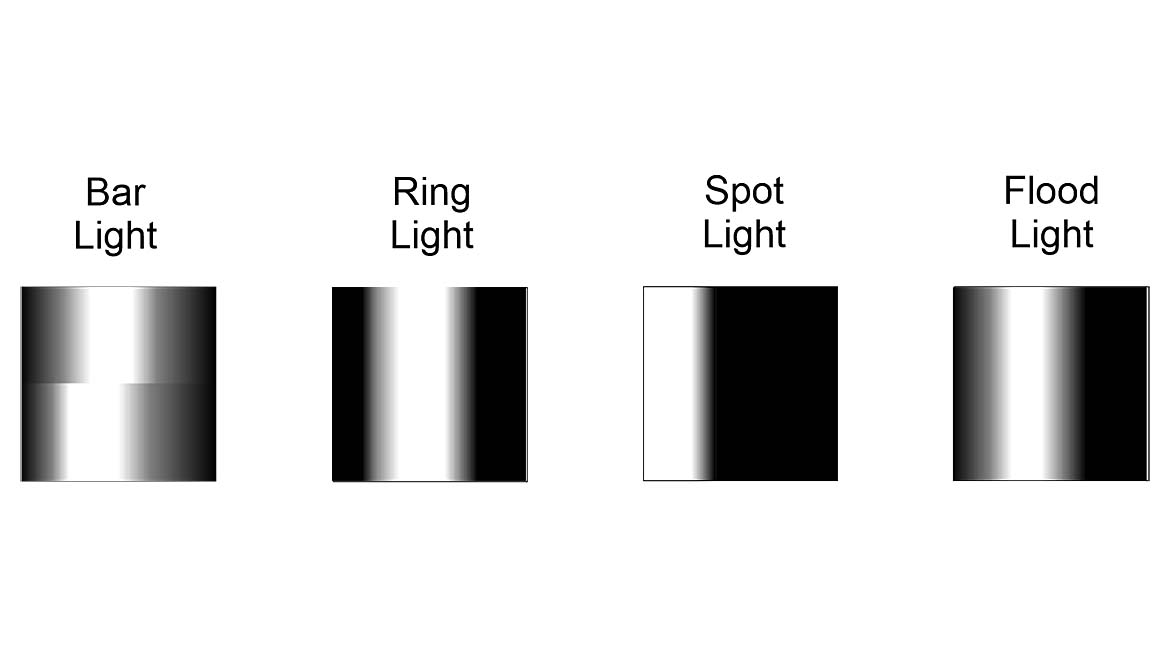
Image Source: Perry West
From the light source mappings covered in the second article in this series, there are four candidates. (See Figure 5.) The spot light would seem to be the best candidate, but it usually gives non-uniform illumination. The flood light and the bar light also appear useful, but their illumination also tends to be somewhat non-uniform. The ring light provides good uniformity and aligns well with the indicated lighting requirement.
Most people could make the light source determination by a quick examination of the mappings. A more procedural approach takes the minimum of the combined mappings from the scene analysis form and the candidate light source. Figure 6 shows this result. The light area indicates where the candidate light source might work. For this example, it might seem that a bright field ring light would work, but that is only partial lighting and may or may not make the star bright. The dark field portion seems like a much better approach.
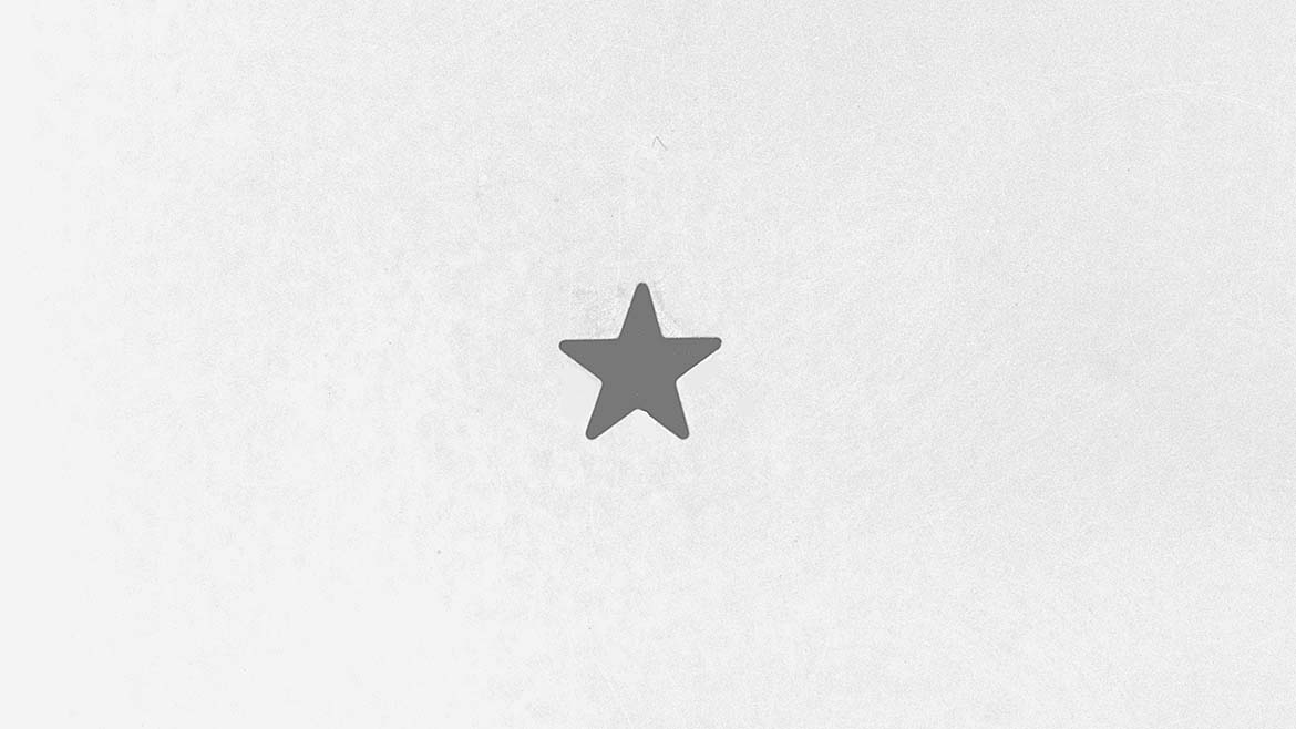
Image Source: Perry West
A test image with the selected light source, shown in Figure 7, confirms the lighting gives good contrast. In acquiring the image, high angle dark field was used — that is, the ring light was higher up and just outside of the illumination “W”. The reason for that was a deficiency in the data provided on the scene analysis form. The star is ever so slightly higher than the background. A lower ring light would have produced brightly reflected light from the edges of the star.
Example 2
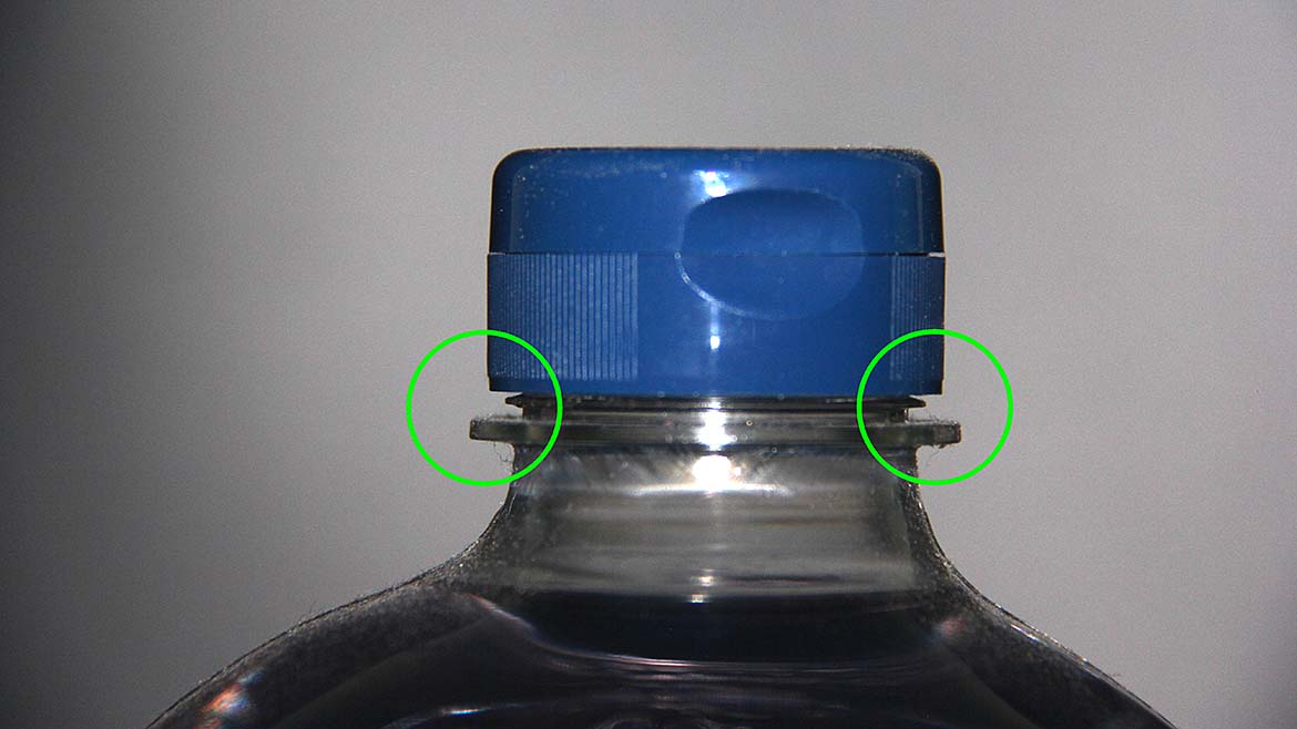
Image Source: Perry West
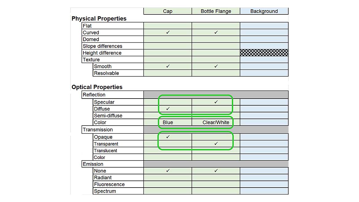
Image Source: Perry West
Let’s look at a second example, finding the gap between a bottle flange and the cap as shown in Figure 8. This gap is important to ensure the cap is screwed on all the way and not tilted. The scene analysis form is shown in Figure 9.
Notice an additional column has been added because there are two features to image against the background: the cap and the flange on the bottle. Also, notice that the background is not filled in. This happens when the background is not specified. However, the background cannot be ignored — it is an integral part of the image and a critical element of contrast. Initial ideas for the background could be a fixed color like black or white with front lighting, or a back light.
The cap is curved (convex) and diffuse. The flange is also curved (convex) and, at least in principle, transparent. Both front lighting and back lighting need consideration.
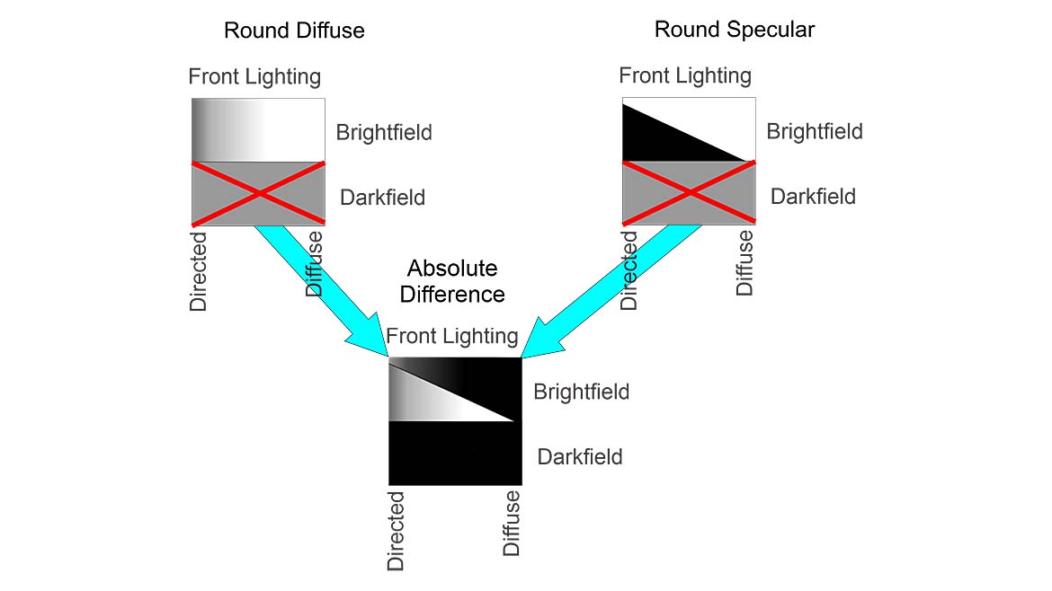
Image Source: Perry West
Figure 10 shows the absolute difference in the mappings of the cap (round diffuse) and the bottle flange (round specular) for front lighting. Unlike the previous example where we wanted contrast between a single feature and its background, in this case, we want the two features, cap and bottle flange, to both contrast against a common background. The dark area in the absolute difference is where the two features can appear similar.
Notice that the absolute difference results in the dark field part of the lighting cube black. This could lead to a misinterpretation, since the dark field portion of both the cap and the bottle flange is curved; their dark field mappings are X’d out. There is no dark field front lighting for a curved surface.
Very diffuse front lighting with a corresponding dark background is one candidate. Since very diffuse front lighting sources, the dome light or the flat dome light, are large and expensive, the search for a lighting solution should continue.
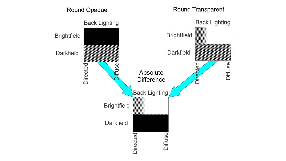
Image Source: Perry West
For back lighting, the absolute difference is shown in Figure 11. Notice the dark field regions for round objects are crosshatched. This indicates that some of the area will be dark and some, typically the edges, will reflect light into the camera.
For bright field back lighting, the opaque cap will be dark, and the transparent bottle will be bright except in the checkered area for directed front lighting where the edges will typically be dark due to refraction and internal reflection. Again, the intention is to have both of the objects, the cap and the bottle flange, be the same against the background. So, we are looking for dark areas in the absolute difference.
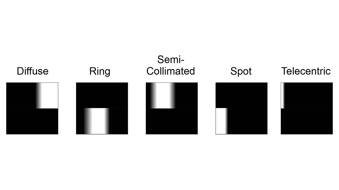
Image Source: Perry West
Either dark field back lighting or directed bright field front lighting are possible candidates. Dark field front lighting requires two lights, one on either side of the bottle, along with a dark background. The amplitudes of the reflections from the cap and bottle may differ, causing unnecessary complexity in image processing.
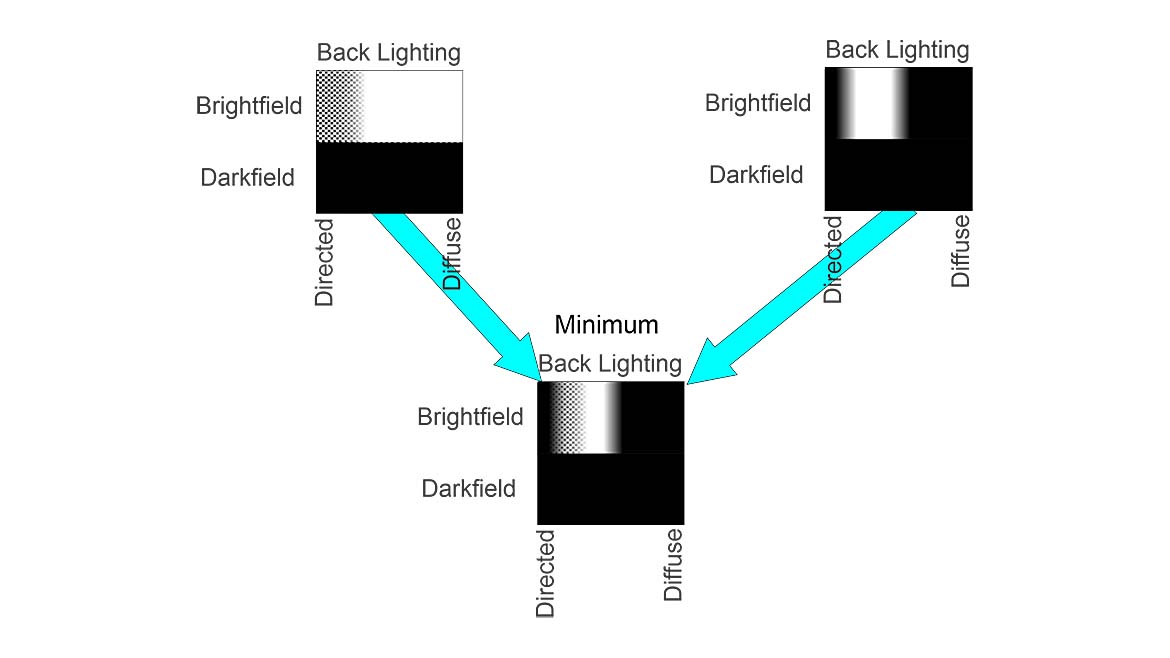
Image Source: Perry West
Directed bright field back lighting is possible and practical. Examining the candidate light sources shown in Figure 12, semi-collimated or telecentric back lights can make the cap dark and bottle edges dark. A telecentric back light is expensive, large, and must be used with a telecentric lens that is also expensive and large. The lens and light will take up significant space. The semi-collimated light source has a good chance of working. The result shown in Figure 13 illustrates this observation.
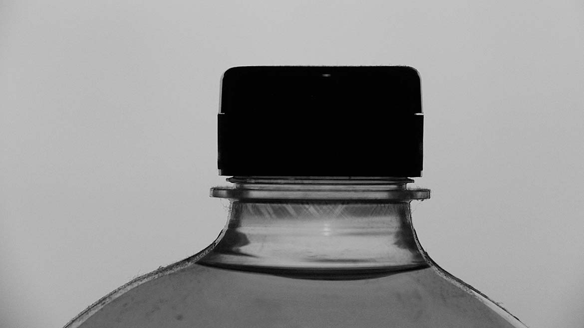
Image Source: Perry West
The selection of a semi-collimated back light gives excellent results, as shown in Figure 14.
Example 3
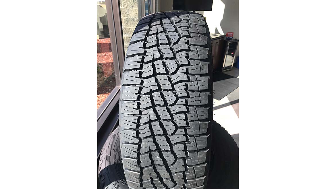
Image Source: Perry West
An interesting example is imaging a tire tread, such as that shown in Figure 15. The tread is comprised of lugs, the raised part, and grooves. Both are composed of black rubber that is diffusely reflective.
One important fact brought out in this example is that black does reflect sufficient light for imaging with very limited exceptions. Obviously, if both features, lugs and grooves, are the same material with the same optical properties, one feature must be the background and the other feature the one that must contrast with the background. The choice is not important since the only difference is the height. For simplicity, the lugs will be considered the background. Figure 16 shows the scene analysis form, identifying that height is the only differentiator.
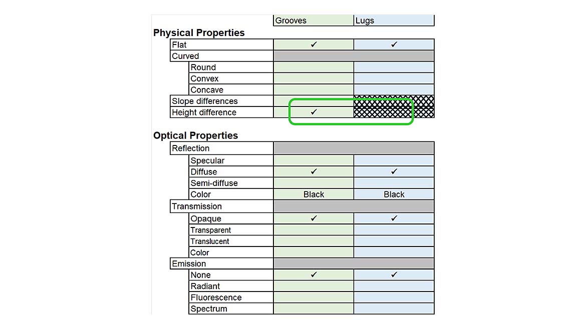
Image Source: Perry West
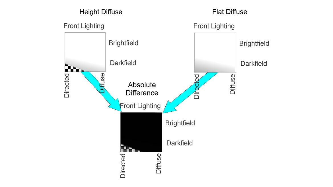
Image Source: Perry West
Following along with the lighting design procedure, take the absolute difference between the flat diffuse surface for the lugs and the height difference for the grooves. It is apparent from Figure 17 that only very directed dark field illumination can create contrast.
There are four candidate light sources with mappings that suggest they will provide directed dark field illumination. These are shown in Figure 18.
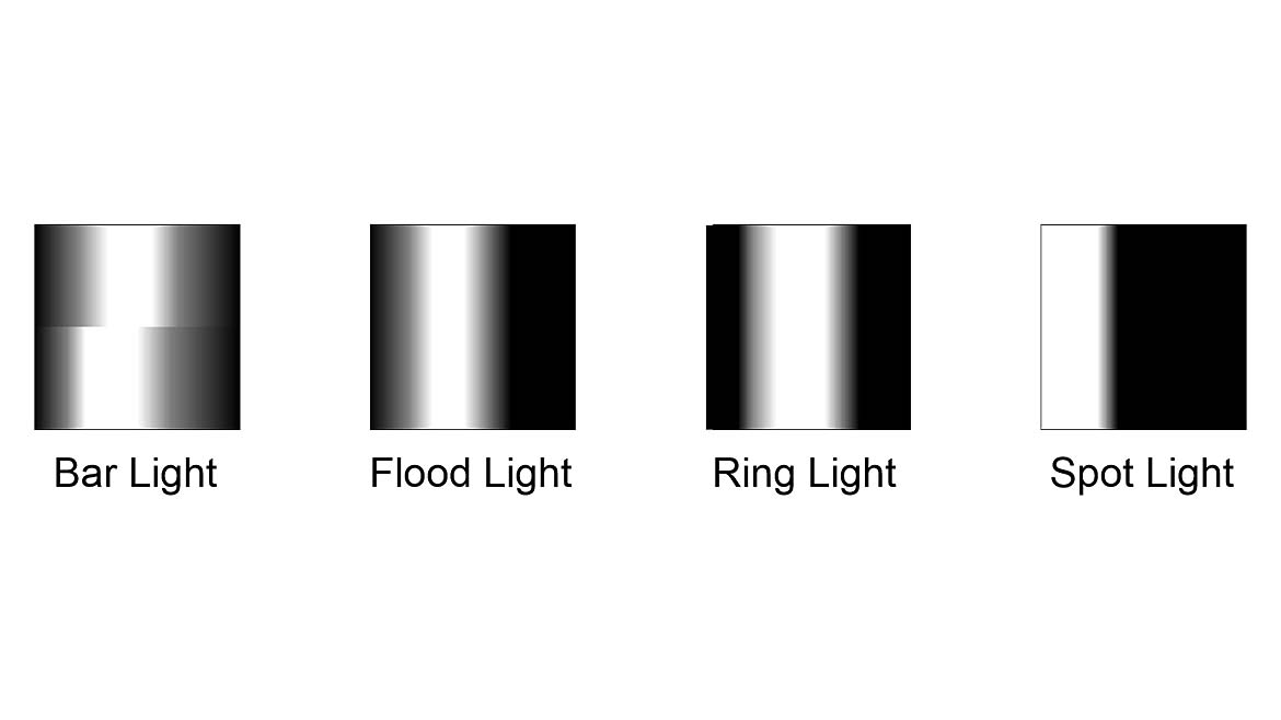
Image Source: Perry West
Of the candidates, the spot light would appear to have the best potential for creating contrast. Spot lights, however, are usually avoided unless necessary because of their potential to create non-uniform illumination.
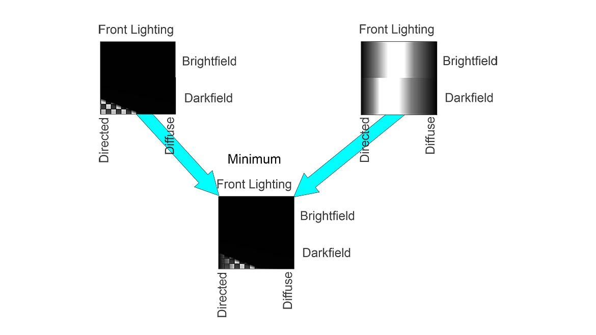
Image Source: Perry West
The flood light is known for producing softer shadows. This application wants high-contrast shadows so the grooves show up dark; so, the flood light is not a good choice. The bar light appears to be a reasonable option.
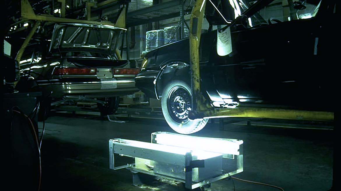
Image Source: Perry West
This application was actually deployed for testing in an auto assembly plant, as shown in Figure 20.
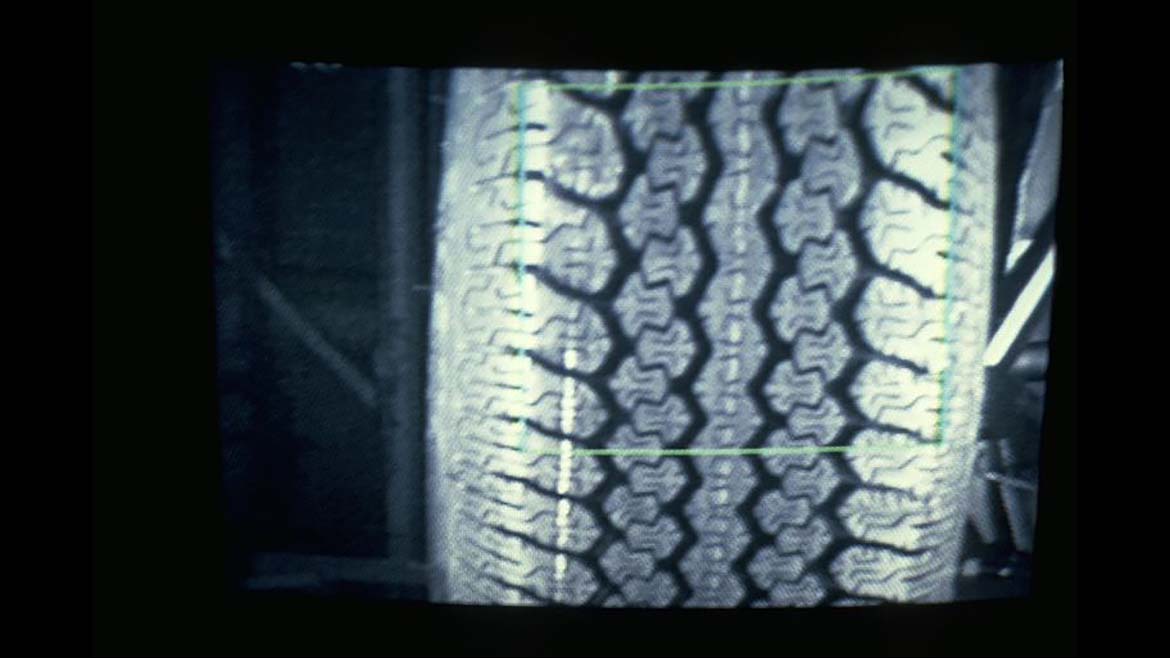
Image Source: Perry West
The image of a tire tread is shown in Figure 21. Note the high contrast of the tread pattern on the tread portion of the tire. Also, notice that where the tread pattern wraps up toward the sidewall, there is much less contrast. The lighting was not designed for the sidewall.
Conclusion
This article shows how mapping light sources onto the lighting cube, along with mapping the scene characteristics onto the lighting cube, can be used to identify a lighting technique with a high likelihood of creating a high-contrast image.
The final article in this series covers the other dimensions of lighting: color, polarization, and intensity. It also identifies certain conditions for which the techniques described in this article are unlikely to return good results and explains the reason why.
Looking for a reprint of this article?
From high-res PDFs to custom plaques, order your copy today!


")

