Lighting
Lighting Design for Machine Vision, Part 5
It took five articles to describe a different way to approach lighting.

This is the fifth and final article in the series on lighting design for machine vision. The first article covered the scene analysis form to identify characteristics of the feature and its background that can create contrast. The second article covered the lighting cube and showed how light sources map onto the cube. The third article covered how characteristics from the scene analysis form map onto the lighting cube. The fourth article covered how to combine the mappings from the feature and its background, along with the mappings for light, to identify a lighting technique that exploits the potential for creating contrast.
This article touches on additional properties of the illumination, specifically color and polarization, and how they are used to create contrast and improve the image. It also touches on illumination intensity. Finally, it gives examples of illumination approaches where the lighting cube could not lead to the best lighting solution.
Color
In developing the lighting cube and the mappings of light sources and information from the scene analysis form onto it, color was not included. Color, though, is a critical component of all machine vision lighting designs. Thoughtfully selecting illumination color enhances contrast further, reduces interference from ambient light, and, for color imaging, helps to ensure accurate color rendition.
As mentioned in the second article in this series, color in machine vision is not limited to wavelengths visible to the human eye; it includes the whole spectrum from infrared through visible and into ultraviolet.
Color, or spectrum, is measured most accurately with a spectroradiometer, a laboratory instrument. This instrument is beyond the practical boundaries of most machine vision engineering facilities. If a detailed spectrum is needed on occasion, there are contract or university laboratories that will contract to provide the data.
For the majority of machine vision applications in the visible spectrum, the human eye, preferably augmented with a set of color filters, is very adequate.
For applications where critical color discrimination is needed, data from a spectroradiometer is required to identify the spectral regions where the feature and background differ the most. Another possible approach to gathering spectral data is to use a hyperspectral camera as an imaging spectrometer.
Color Wheel
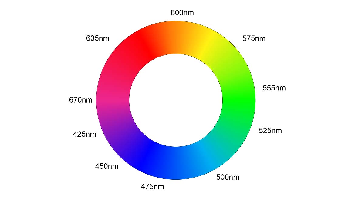
Image Source: Perry West
For applications not requiring a color camera, the color wheel, shown in Figure 1, is a good aid to picking lighting color to enhance contrast. For any feature or background color, illumination of a similar color will make it brighter. Illumination with a color opposite the feature or background color will make the feature appear darker. This works well for saturated colors. For pastel colors, the contribution to contrast of illumination color will be less pronounced.
Spectrum
When working in the infrared region, with wavelengths longer than about 700nm, where the human eye cannot provide any color information, some instrumentation is needed. The most straightforward approach is an infrared camera, a broad spectrum infrared light source, and some infrared bandpass filters.
Reducing Ambient Light Interference
For applications that do not require color imaging to capture a range of colors, narrow-band illumination (e.g., red, green, or blue), used to create contrast along with a matching filter over the camera lens, helps reduce the effect of ambient light by an order of magnitude or more. In fact, a best practice in machine vision is to always use a filter over the camera’s image sensor or lens that rejects light wavelengths that are not of interest. This ensures ambient light contribution is minimized, leading to better contrast.
Returning to an example in the fourth article in this series, imaging a gold star on a blue background, it was shown that a dark field ring light gave very good contrast. Contrast would be further improved, and the application made more robust by also using a selected illumination color. A blue light source with a matching blue bandpass filter over the lens will enhance the contrast between the blue background and the gold star, because yellow reflects all colors except blue.
Polarization
One property of light is its polarization. All light sources, with the exception of some lasers, provide unpolarized light. Transmitting unpolarized light through a linear polarizer gives linearly polarized light.
Polarizer-Analyzer
A differentiating characteristic between specular and diffuse reflection is how polarized light is affected during reflection. Diffuse surfaces scatter incident light; the incident light’s polarization is randomly altered by the scattering, making it unpolarized. Specular surfaces reflect polarized light and, because there is no scattering, the polarization is maintained.
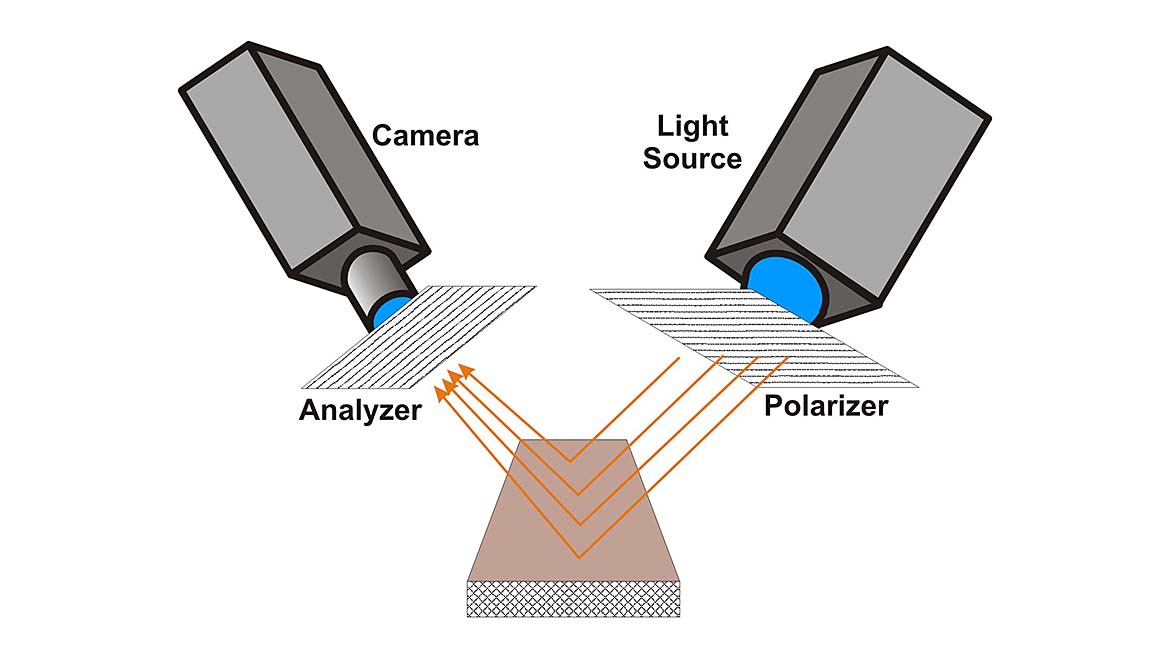
Image Source: Perry West
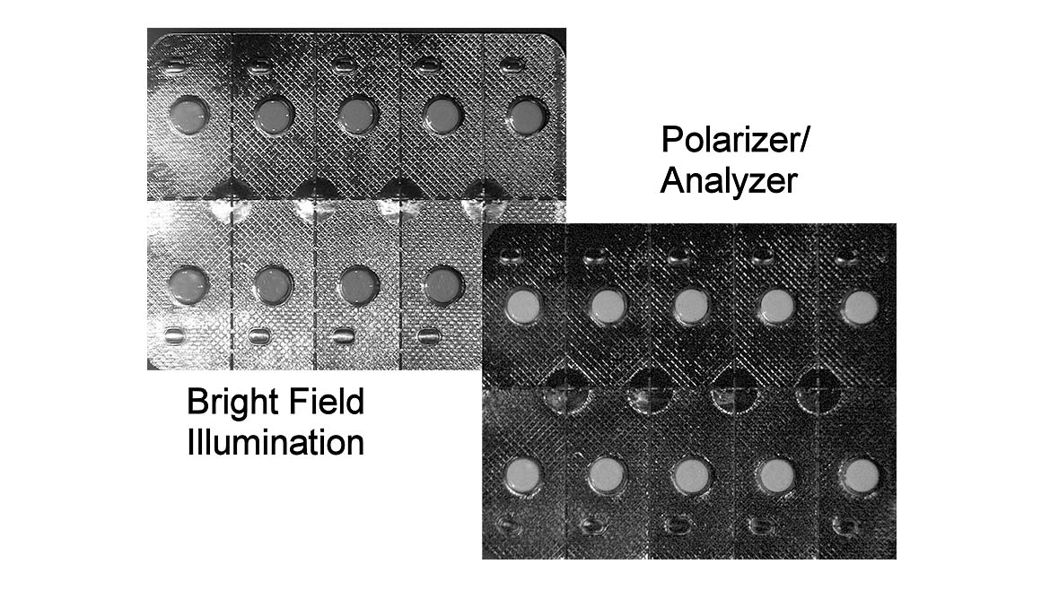
Image Source: Perry West
This difference in reflection of polarized light allows for a technique called a polarizer-analyzer, shown in Figure 2. A scene is illuminated with linear polarized light, usually created by a linear polarizer placed over the light source. Reflection off the scene will have areas of specular reflection maintaining polarization, and areas of diffuse reflection reflecting light that has become unpolarized. A second linear polarizer, called an analyzer, is placed over the camera’s lens and aligned such that it blocks polarized light from the light source. Specularly reflective surfaces appear dark in the image because their polarized reflections are blocked by the analyzer. Diffusely reflective surfaces will appear brighter in the image because a good portion of the unpolarized reflected light passes through the analyzer. Figure 3 shows the effect of the polarizer/analyzer on a blister pack with pills.
This is one technique for imaging specular surfaces. The other technique is to use a large diffuse light, such as a dome light or flat dome light. The major difference is the polarizer-analyzer makes the specular surface dark and the diffuse surface bright. Using a large diffuse light source makes both the specular and diffuse surfaces bright. The polarizer-analyzer approach has the advantage that it is less expensive and usually less space-consuming than a large diffuse light source. The diffuse light source has the advantage that it does not require achieving and maintaining the precise alignment between the polarizer and analyzer.
The mapping of surfaces and light sources onto the lighting cube, as covered in parts 3 and 4 of this series of articles, doesn’t provide a path to identify the polarizer/analyzer as a possible illumination technique.
Birefringence
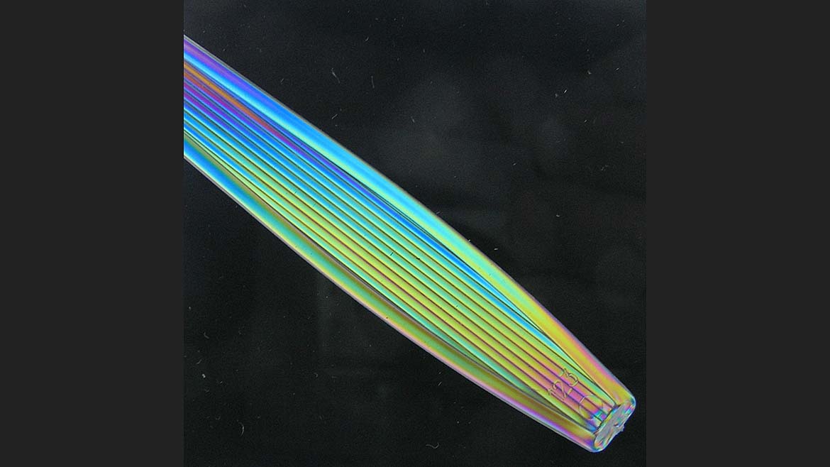
Image Source: Perry West
Some transparent materials exhibit a phenomenon where they change the polarization of light. Several transparent plastics have this ability. When imaging these parts using a back light, if the back light is polarized and an analyzing polarizer is used over the lens to block the polarization of the back light, a birefringent material placed between the polarizer and analyzer changes the polarization of the light, letting some of the light through the analyzer.
Neither the scene analysis form nor the mappings onto the lighting cube currently identify and deal with birefringence. If it is a property that you might use in designing illumination, you will need to rely on your understanding of optics.
Reflection and Polarization
Another aspect of polarized light is reflection off a specular surface, such as a mirror or prism used to fold the optical path, results in the reflected light becoming partially polarized. Partial polarization occurs because the surface reflectivity depends on the incident light’s polarization. Light with polarization perpendicular to the plane of incidence (the plane defined by both the incident and reflected rays) is strongly reflected. Light with polarization parallel to the plane of incidence is reflected less strongly. The degree of partial polarization is given by Fresnel’s equations and depends on the reflective material and the angle of incidence.
Intensity
The light must provide enough power to ensure an adequate exposure by the camera. Exposure is light energy: that is, the product of light power and exposure time. Contemporary machine vision cameras have exposure time control that can be used in conjunction with the light source to create adequate exposure. Some applications are time-critical or need to deal with part motion and minimize blur in the image. In those cases, there is an upper bound on the exposure time. Most modern LED light sources for machine vision can be strobed and overdriven to give more light energy for a short exposure duration.
At this time, there is no easy way to calculate the needed light intensity. It would take knowing the camera’s sensitivity (which is not its QE), detailed information on the part’s surface reflectance or transmittance, and an intensity map of the light source under the anticipated use conditions.
Outlier Examples
To further illustrate some limitations of the technique presented in this series of articles, a couple of actual examples are provided below.
Transparent Object/Absent Background
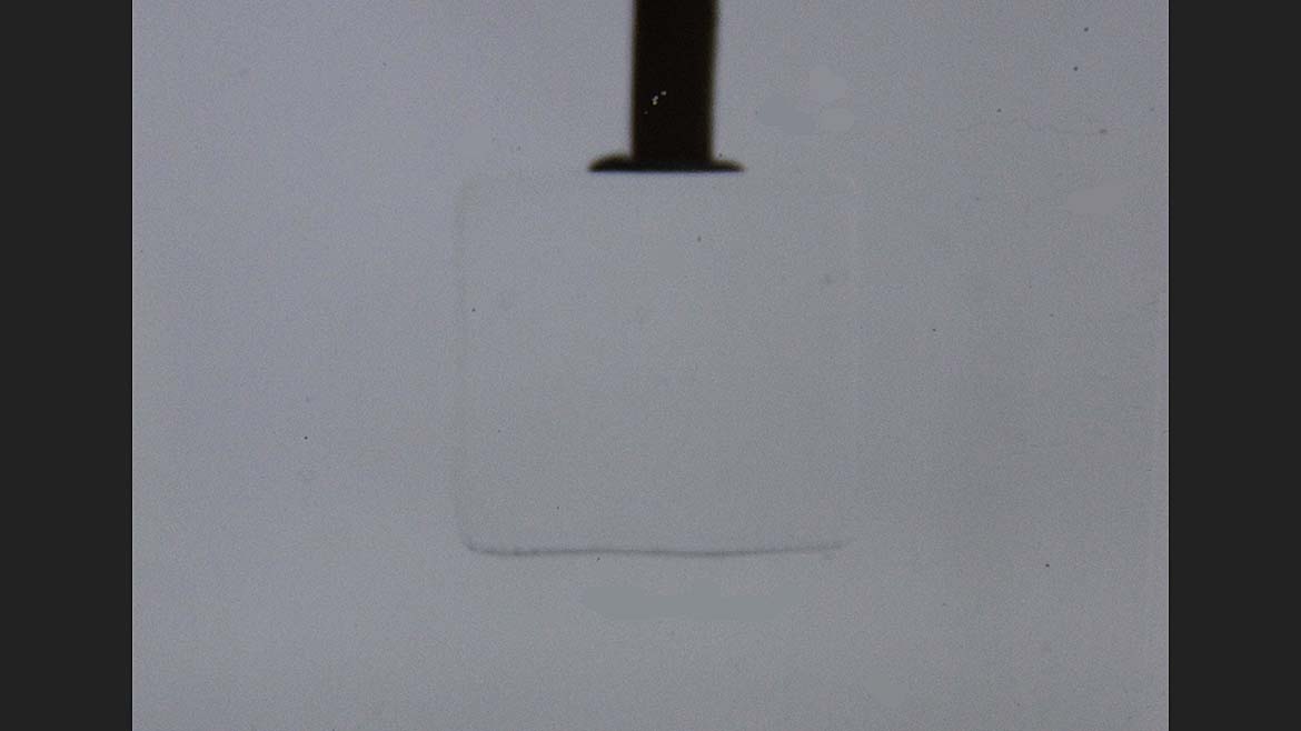
Image Source: Perry West
There was the case where it was necessary to image a clear, transparent part in a water bath that is also clear and transparent. How can contrast be achieved when the object and the background are both clear, transparent materials? Clearly, the scene analysis form won’t show any characteristic that will create contrast.
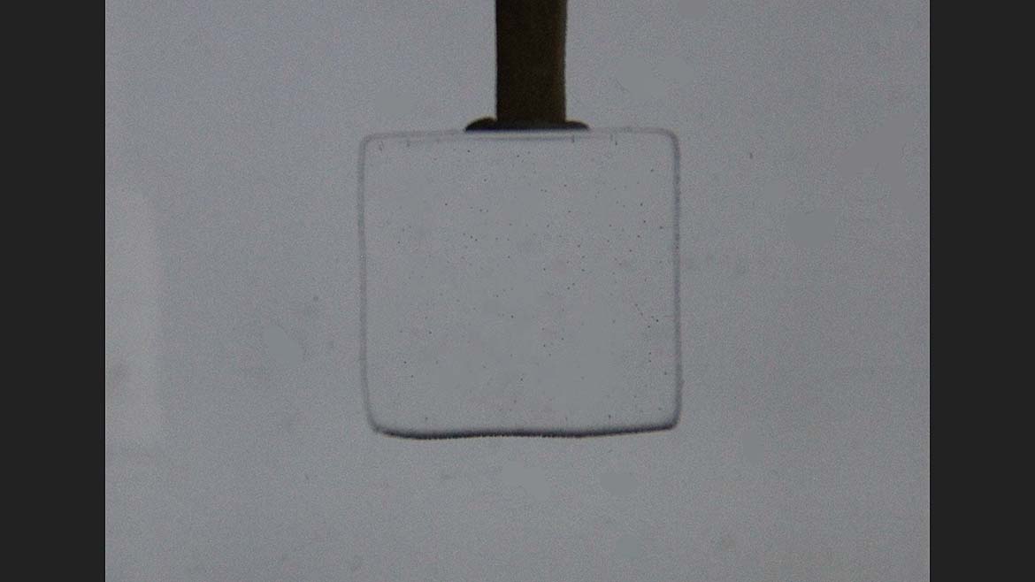
Image Source: Perry West
You need to ask what the difference is between the part and the water. The answer must be: indices of refraction. If the indices are identical, the part will disappear in the water bath, and no lighting technique can distinguish the part. However, if the indices of refraction differ, light will be refracted at the interface between the part and the water.
Diffuse lighting leads to a variety of refractions that cancel themselves out, leaving the part undetectable (see Figure 5). A collimated light source, or even a semi-collimated light source, will make the refraction evident, leading to a dark outline of the part (see Figure 6).
In the actual application, the part was held by hand, while the vision system made a measurement of its size. The uncertainty in position required the use of a telecentric lens to eliminate magnification variations. An option for collimated illumination was a telecentric illumination—a telecentric lens mated to a light rather than a camera. However, telecentric lenses are large and expensive. Use of a telecentric lens would make the imaging module too large and very expensive. An alternative approach was employed. A telecentric lens with coaxial illumination imaged and illuminated the part. A retroreflective sheet was placed behind the container with water to reflect the illumination directly back to the lens. The configuration gave very good edge contrast while saving space and cost.
Double Layer
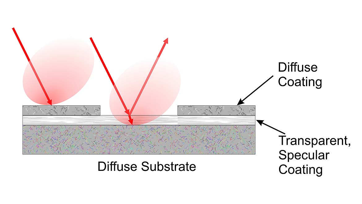
Image Source: Perry West
Take the case where the surface of a part has multiple layers of material. For example, a solar panel inspection looked at solar cells that had a translucent layer over a clear transparent layer that was over a diffusely reflecting substrate material, as diagramed in Figure 7. The imaging requirement was to make voids in the top translucent material evident.
The scene analysis form is not set up to work with multiple layers of materials. In this case, it would need to consider a foreground translucent layer, an intermediate transparent layer, and a background diffusely reflecting layer. Because the diffusely reflecting layer is opaque, backlighting is unusable. Front lighting using reflection is necessary.
One idea would be to create contrast between the top translucent layer and the transparent layer below it, while ignoring the diffusely reflecting surface below the transparent layer. The top translucent layer provides diffuse reflection. The layer beneath that, being transparent, reflects some light and transmits much of it onto the substrate, which then diffusely reflects it.
It would seem that dark field lighting would make the translucent layer bright due to its scattering, and the transparent layer dark, since reflections would be specular. However, dark field lighting didn’t give good contrast. Much of the light falling on the transparent layer passed through it to the diffusely reflecting layer below. The result was very low contrast between the translucent and the transparent layers.
Reversing the approach and looking for a lighting technique that would make the transparent layer bright and the translucent layer dark led to the use of a condenser light source.
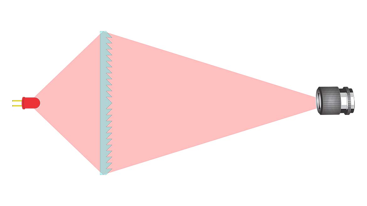
Image Source: Perry West
A condenser light source is one that focuses all its light into the lens. The condenser light source is similar to the collimated light source in having its light rays travel mostly in an intended direction rather than in a wide angle of directions common with most light sources. While a collimated light source has parallel rays, or, more correctly, parallel bundles, of light, the condenser source has directed rays or bundles, though not parallel.
In this case, the light and camera were angled so that specular reflections off the transparent surface reached the camera’s lens. Some of the scattered light off the translucent surface reached the lens, but it was only a very small fraction of the incident light. A high contrast image was achieved. Camera calibration corrected for keystone distortion due to the camera’s angle.
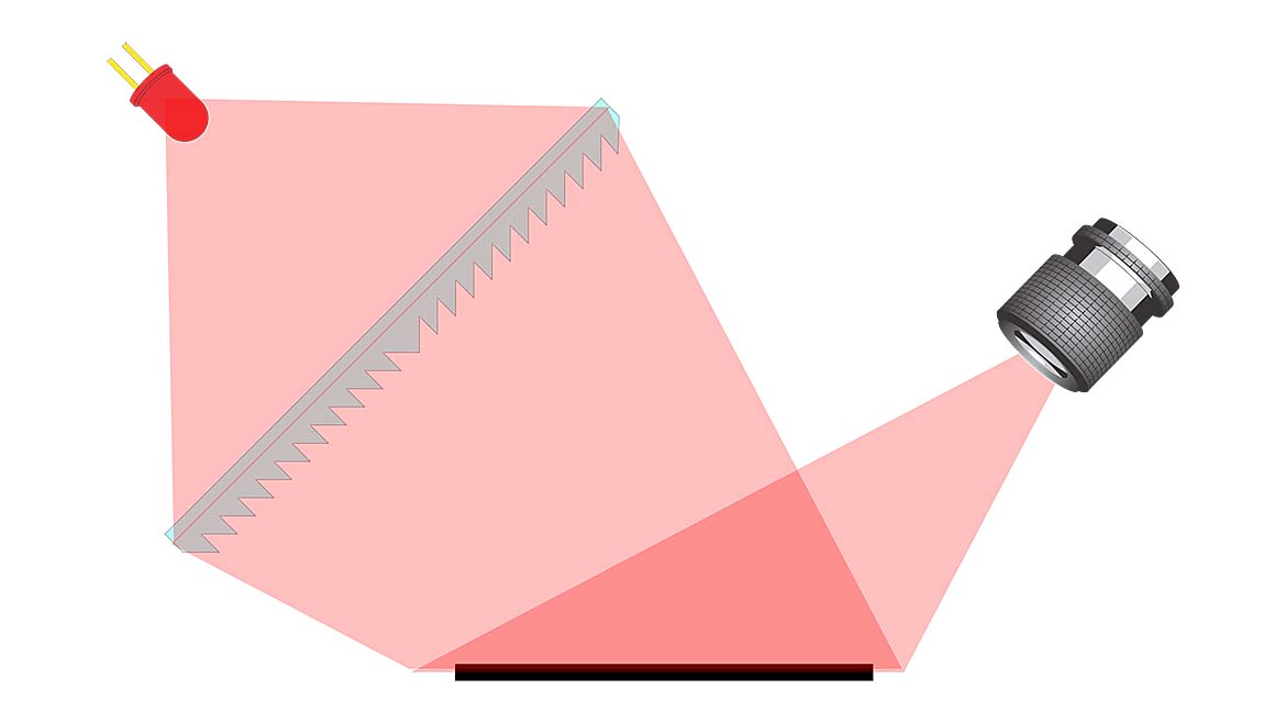
Image Source: Perry West
There are few, if any, condenser light sources commercially available for machine vision illumination. Each condenser light is very application-specific for a given field-of-view and a given working distance.
Conclusion
It took five articles to describe a different way to approach lighting. The first four covered the scene analysis form, the lighting cube, mapping light sources onto the lighting cube, mapping contrast-creating differences from the scene analysis form onto the lighting cube, finding out what areas of the lighting cube will exploit the contrasting characteristics, and identifying which light source can exploit the contrast characteristics using the lighting cube.
This final article touched on the remaining three of the six lighting dimensions: color, polarization, and intensity. It also gave a couple of examples where using the scene analysis form and the lighting cube does not lead to a solution, yet your understanding of how light interacts with material still enables you to find a solution.
Looking for a reprint of this article?
From high-res PDFs to custom plaques, order your copy today!


