Vision & Sensors | Vision
Identifying the Best Technology for Your 3D Vision Application
Unlocking the potential in 3D Vision today.
3D Vision technology is revolutionizing a broad range of sectors, from large-scale construction mapping to nanometer level inspection in complex manufacturing processes, through to the detailed imaging of body parts in the medical industry.
The diversity of applications makes the 3D Vision field extremely fragmented, making it difficult to identify the technology that will best fit a given application in terms of overall value.
Firstly, a technique that can best fit the requirements needs to be selected. This is already a challenging exercise, as there are many solutions to depth sensing: ranging from laser based systems (for extreme precision levels such as OCT), laser profiling, confocal imaging, to passive and active stereo vision for middle ranges, right through to Time-of-Flight (ToF) based systems.
Once one of these techniques has been identified as a good fit, a complex set of trade-offs needs to be navigated through. The foundation of a 3D camera and system are the illumination, optics, and processing, all put together around a sensor or module component. The selection of the right 3D sensing component can be crucial when it comes to delivering the right value.
In this article, a method to identify the techniques that best fit an application are discussed, together with examples of the trade-offs to consider when it comes to selecting a sensor or module component, and how this can be key to unlocking the differentiation needed in your product.
From Complexity to Clarity: The 6-Domains Method

Part of the approach to addressing 3D Vision challenges is to start by mapping requirements into six key application domains:
- Vision Range - how far away is the target, what’s the required field-of-view, are there any occlusion issues?
- Depth accuracy and precision - how repeatable and reliable must depth sensing or measurements be?
- Image pipeline - what image format and frame rate are needed, and how will the data be processed (embedded System-on-Chip, or PC, or FPGA)?
- Scene characteristics - what are the features of the target scene? (indoor/outdoor, light sources, motion speed, potential interference sources, specular reflection, HDR requirements, etc.)
- Lighting specification - power, wavelength constraints, and eye safety compliance
- SWAP-C - are there constraints in Size, Weight, Power and Cost?
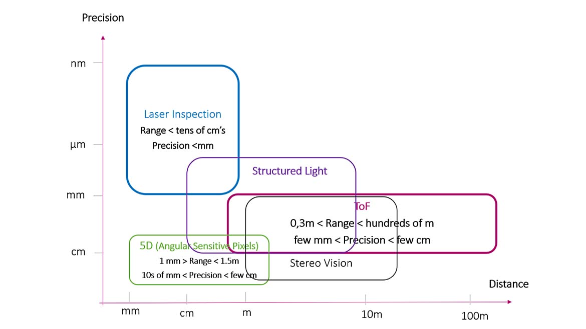
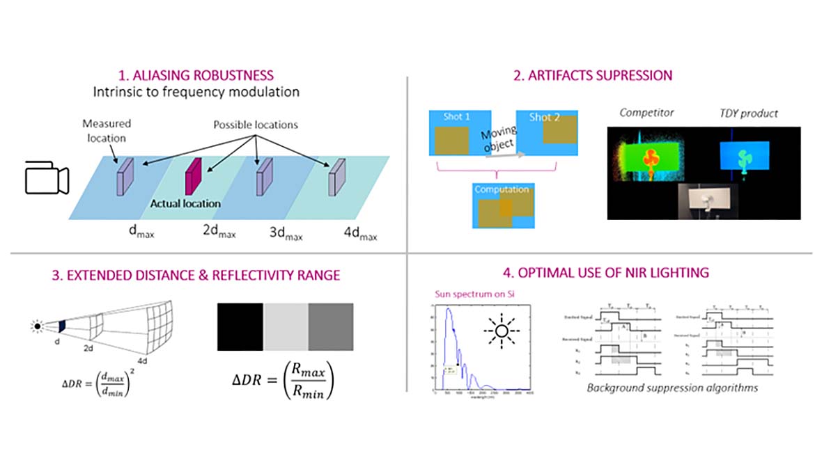
We’ll begin by considering the first two domains to narrow the list down to one or two techniques. The schematic above summarizes how 3D techniques can be mapped to these first two domains and shows how overlap exists in certain application areas.
The other four domains help resolve the overlap and narrow the list of techniques down to the one that will deliver the right product value. Once a technique has been identified, the next step is to find the right implementation of it.
Typically, Time-of-Flight systems have a number of possible implementations, ranging from SPAD-based direct Time-of-Flight to multi-tap CMOS based indirect Time-of-Flight, which can also have implications on system characteristics.
In the section below, a set of practical examples are discussed, using this method and highlighting the importance of the sensor component to the value of the final product.
Zooming In: Some Practical Examples
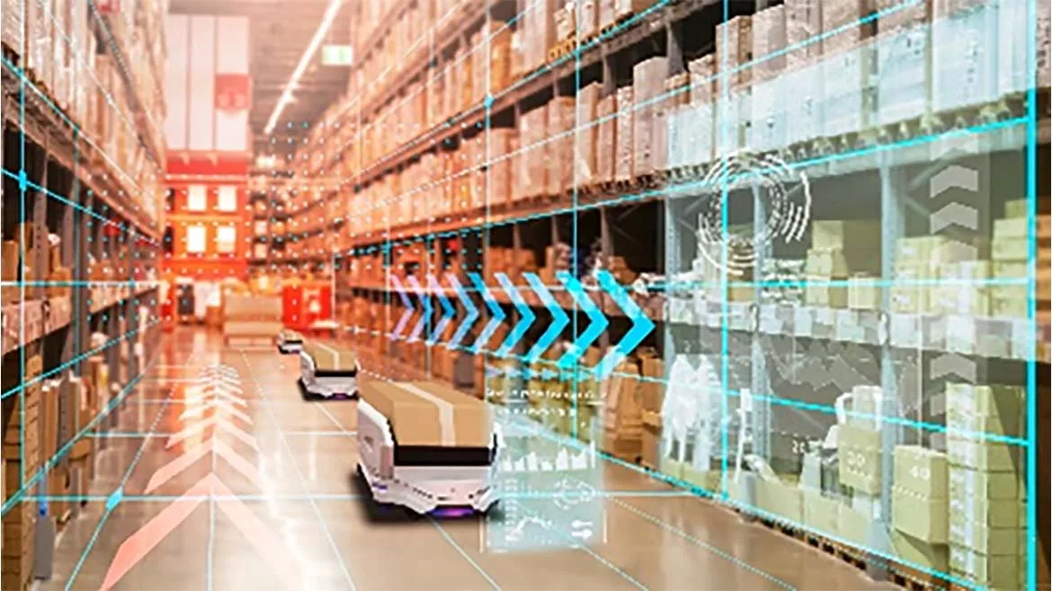
3D Vision is enabling considerable innovation in logistics. The perception of depth is of paramount importance in applications such as robot navigation, fleet coordination and most notably, parcel dimensioning. Each of these applications have different requirements, with completely different 3D Vision techniques being implemented for each challenge.

Taking the case of robot navigation, these generally require depth perception with millimeter accuracy at a range of few meters (30cm to 2m). With these parameters, laser profiling techniques can already be eliminated, and the focus be on either a Time-of-Flight or a stereo vision based solution.
Putting safety considerations aside (for which 2D LiDAR is generally the de-facto choice for Autonomous Mobile Robots), robots in logistics often need to detect what type of object is in the area of proximity (for instance whether it is another robot, a person, or a static object).
Typically, stereo vision can be a good choice for these distance ranges, as it offers high resolution (and therefore has more capability to capture an object’s details), and millimeter level precision. However, if the objects need to be detected in real-time, stereo has a latency limitation of a few hundreds of a millisecond due to the computation of the depth map that is outputted from the two CMOS sensors used.
Alternatively, Time-of-Flight techniques can also comply with the range and precision levels targeted by logistics robots. For this application, latency times are in the order of tens of milliseconds, making ToF a very good fit.
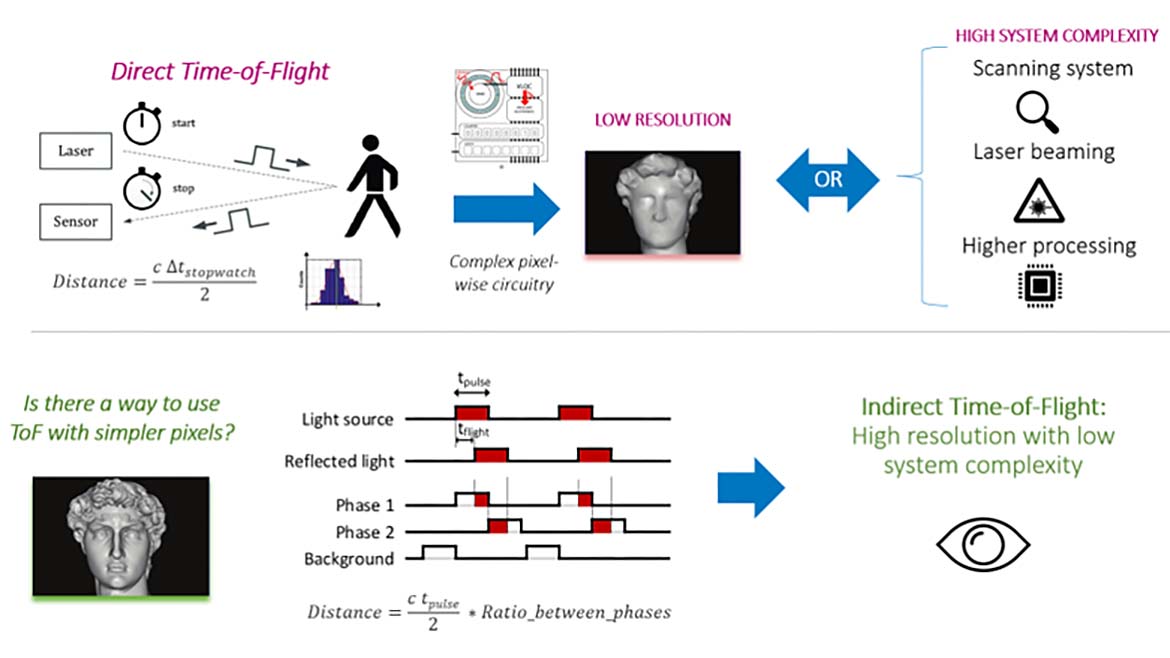
When looking at the implementation, ToF systems can be either direct or indirect. The main difference is that indirect ToF sensors, while providing generally lower performance at long distances (tens of meters), enable higher resolutions, making them a good fit for complex object identification.
This is why, when it comes to identifying objects in industrial environments, indirect Time-of-Flight can be an excellent choice. Finally, when it comes to the sensor component, the rest of the requirements mapped into the six application domains need to be taken into consideration.
For this application, robots can operate in areas subject to ambient light or illumination coming from other systems, while also having to comply with stringent eye safety measures to take into account the presence of people. In addition, the objects to be detected may be moving (or the robot itself), and of different reflectivity.
Selecting the right ToF sensor is key to properly tackling the above challenges. In this scenario, a sensor with a big pixel pitch (in the order of 10 µm) will enable the optimal use of light power (therefore making it eye safe), while still delivering a good performance. On-chip HDR features are also the key to supporting a wide diversity of object materials without compromising latency or frame rate.
Another example of how depth sensing can provide innovation in logistics robot navigation is for docking systems. The use of vision for depth perception can enable implementation without additional infrastructure. For this application, the vision ranges are of a few centimeters, also requiring millimeter level precision.
Not many 3D Vision techniques can be mapped in this area, as stereo vision is limited for short ranges (objects are blurry below tens of centimeter ranges because of occlusion), and Time-of-Flight has the intrinsic limitation of saturating at too short distances (below 30-40 cm).
This is why we have engineered a passive technique to provide differentiating 2D + 3D depth sensing at distance ranges starting from a few millimeters up to 2 meters. This is called the Angular Sensitive Pixels technique. It provides sparse and denser depth maps based on contrast detection, on top of a 1,920 x 1,080 pixel 2D image. It uses no specific illumination and natively offers the possibility of direct 2D image fusion with 3D depth data. This technology is ideal for the pervasive deployment of more AI/ML processing at the Edge. Individual sensors and pre-calibrated imaging modules which encompass this unique innovation are already available on the machine vision market.
Conclusion

In a fragmented 3D Vision landscape, differentiation lies in understanding your application’s exact requirements and having the ability to map them against the right technology. Once a technology has been identified, it all comes down to navigating through a set of implementation trade-offs that, when properly balanced, will deliver the required value and problem-solving solution.
Looking for a reprint of this article?
From high-res PDFs to custom plaques, order your copy today!


