Measurement
Mastering with Deviations for Increased Gaging Performance
The time has come to adopt master deviations as a necessary practice in modern manufacturing processes.

Image Source: Mahr
The gaging setting standard is one of those metrology foundations that does not get much respect. These typically take the form of a master setting ring, disc, or plug. Take, for example, a 10mm master setting ring. One can purchase a 10mm master ring, class XX, for about the same cost as a high-quality digital caliper.
Because of its nature, a digital caliper is one of the most universal measuring tools, making direct reading measurements anywhere over its 150 mm measuring range. In contrast, a master setting ring is good for one setting – the size it is manufactured to.
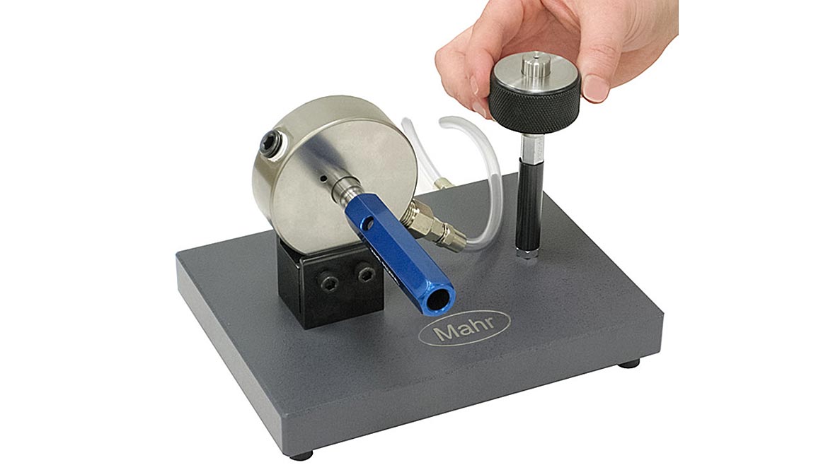
A caliper, on the other hand, is not the most accurate measuring instrument. With its course resolution, lower accuracy internal scale, and obvious user influence, this device certainly is not optimized for sub-micron measurement. Alternatively, a comparative gage, which can be made robust and designed to minimize operator influence while employing a very high resolution and accuracy sensor, can achieve sub-micron performance. However, the comparative gage needs a starting point or zero reference to accomplish this. This is where the master setting standard comes in. It is the foundation for comparative measurement and is where its value starts to shine.
Comparative gages excel in very high-performance manufacturing applications, such as hydraulic valves, medical implants, fuel injectors, and aerospace components, and the importance of a good setting master is critical. Getting the most out of the master and using it properly in the setting of a gaging station will improve performance and potentially reduce future master and calibration costs.
What are the Setting Standards?
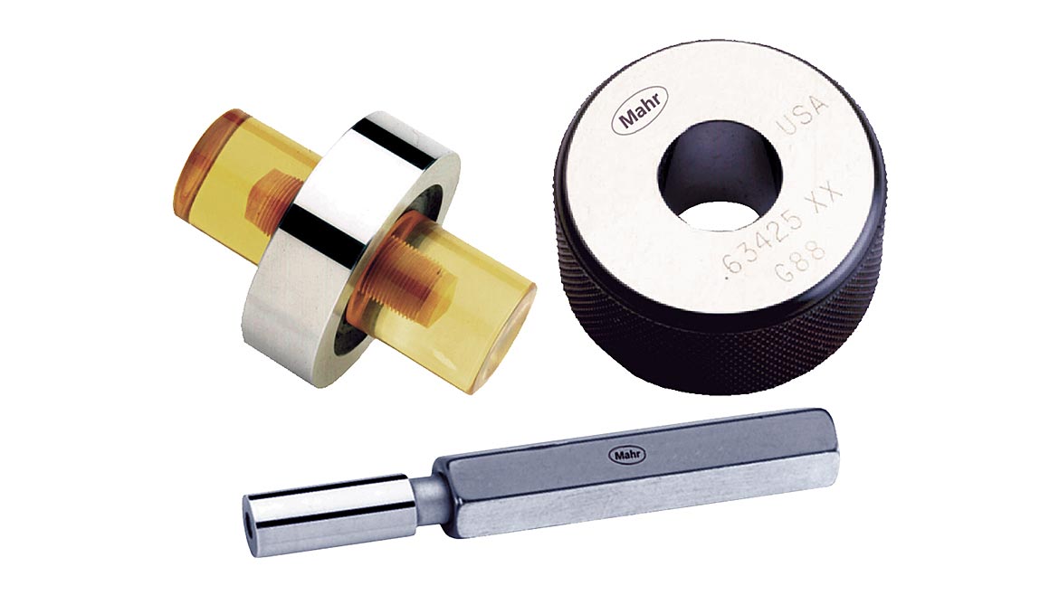
A master ring, or ring gage, is essentially a bore of known dimension. The precision hole is often used as a setting master for variable inside-diameter gages (such as bore gages, air tooling, and mechanical plug gages), for go/no-go mastering of fixed ID gages, and for go/no-go OD inspection of male cylindrical workpieces. These are similar to master discs and plugs for OD gaging and similar in use and manufacturing/certification standards.
Master ring gages are made from hardened steel. In the U.S., they are based on long-ago-defined American Gage Design (AGD) standards (updated over the years) to newer ASME standards, which define sizes of blanks, forms, and finishes. They are classed by level of accuracy, with XXX indicating the tightest tolerances; XX, X, and Y being intermediate grades; and Z being the lowest.
Class tolerances vary by size. Larger sizes have more open tolerances since they are more complex to manufacture.
For example, the following tolerances would apply to a 10.000 mm master ring:
0.25um
0.5um
1um
Of course, the better the class is, the more expensive it is. The XXX ring is manufactured to a tighter tolerance, and there is a cost involved with this. It may take longer to manufacture, require the skill of a higher-paid technician, or if something goes wrong—say the tolerance is missed by parts of a micron—it may have to be remanufactured, thus costing more to manufacture and longer to deliver.
Come to think about it, that individually made 10mm hole in a piece of steel—manufactured and certified to within parts of a micron and used for potentially life and death situations—is a pretty good value for the price.
For more senior users, the “rule of thumb” for master selection is to choose a master with a tolerance that is 10% of the part tolerance. For instance, manufacturing parts with a tolerance of ±0.015mm typically requires a master with a tolerance of ±1.5um or better. Combined with the gage’s performance, this should provide adequate assurance of a good measurement process. For this application, a Class X master would be the best choice.
It’s usually not worthwhile to buy more accuracy than is needed since it costs more, doesn’t improve the gaging accuracy, and the master will lose calibration faster. On the other hand, when manufacturing to extremely tight tolerances, one might need a ratio of 4:1 or even 3:1 between gage and standard simply because the master cannot be manufactured and inspected using a 10:1 rule.
A Quick Note About Measurement Uncertainty
When the setting master is made and measured, there is uncertainty in the certification process. The manufacturer’s calibration facility has worked with a certifying body to develop methods for the item’s certification and potential errors in that process. This is the “uncertainty” noted on the certificate accompanying the master ring, disc, or plug.
Gage blocks are a “primary” standard; they are documented and traceable back to an official, absolute standard. In the U.S., it is to the National Institute of Standards and Technology (NIST). Documentation makes it possible to determine the level of accuracy in a given gage block. Master rings and discs, in contrast, are generally considered to be secondary standards because their size is established by reference to gage blocks. Traceability is one step further removed, which implies a greater level of uncertainty.
Uncertainty is similar to golf scores. In both cases, the lower number is better. While uncertainty isn’t necessarily cumulative, it’s easy to see how levels that may be insignificant for tolerances of ±50um or ±25um can become critical when measuring to ±2um.
All this concern with mastering, calibration, and external standards is not an intellectual exercise of interest only to a chosen few: any manufacturer hoping to meet sub-micron tolerances, obtain ISO 9000 certification, or satisfy many other industry standards may be required to reference its measurement methods to officially recognized physical standards.
A Flaw in Master Use?
U.S. manufacturers typically base their comparative gages on a zero or nominal master due to how master standards were originally written. This makes it easy for the gage operator because all they are required to do is put the nominal master on the gage and zero it to the nominal size of the master (or to zero if using a deviation from zero to classify the parts). However, since this class has an error limit, as seen above, one can say that when the master is used to zero the gage, the operator ignores that deviation within the limits. That known deviation may not be critical in many cases where tolerances are not tight. But when trying to qualify parts where the tolerance is a few microns, the deviation of the master from its target size can be the difference from a part in or out of its tolerance.
As tolerances in critical industries continue to get tighter, creating better masters, certified to the precise size etched on them, is becoming increasingly challenging. Therefore, it is vital to know the actual size of the master. Masters can be certified to their class (the XXX, XX, X, etc.), or they can be certified to their size.
Masters are accompanied by documentation certifying their actual size to comply with ISO and other standards, confirming adherence within class-specific tolerances. In simpler terms, a certified master has undergone testing and verification to meet specific standards. It has a certificate documenting its size at various locations along with the calibration lab’s measurement uncertainty.
The difference between the nominal class size—what the master is supposed to be—and what the size of the master is actually measured to be is referred to as the Master Deviation. The uncertainty of this number is most likely smaller than the deviations generally found with a master made to a specific class size. By using the master deviation from the calibration certificate and setting the gage to the actual master size (rather than nominal zero), XX rings can deliver performance comparable to XXX rings. The overall accuracy of the measurement can be improved, often using a lower-class master. This approach not only reduces costs but also potentially accelerates gage delivery.
For example, a 10mm class XXX master ring has a potential error of ±0.25um. A 10mm class X ring has a tolerance range, or possible error, of ±0.5µm. Documentation shows it is off by some specific amount, say +0.4um. Many gages, such as air tooling, bench amplifiers, and even some good digital and dial comparators, can resolve to 0.1 or even 0.01um), and by “dialing in” this master deviation when zeroing the gage, it may be able to squeeze an extra couple sub-microns of accuracy out of a gage that is measuring a ±2um tolerance (the difference between the ±0.25um Class XXX tolerance and the +0.4µm gage setting). This enhancement yields a 20% improvement in process efficiency while reducing master costs by 50%, providing significant resource optimization opportunities.
Breaking the “Just Zero the Gage” Philosophy
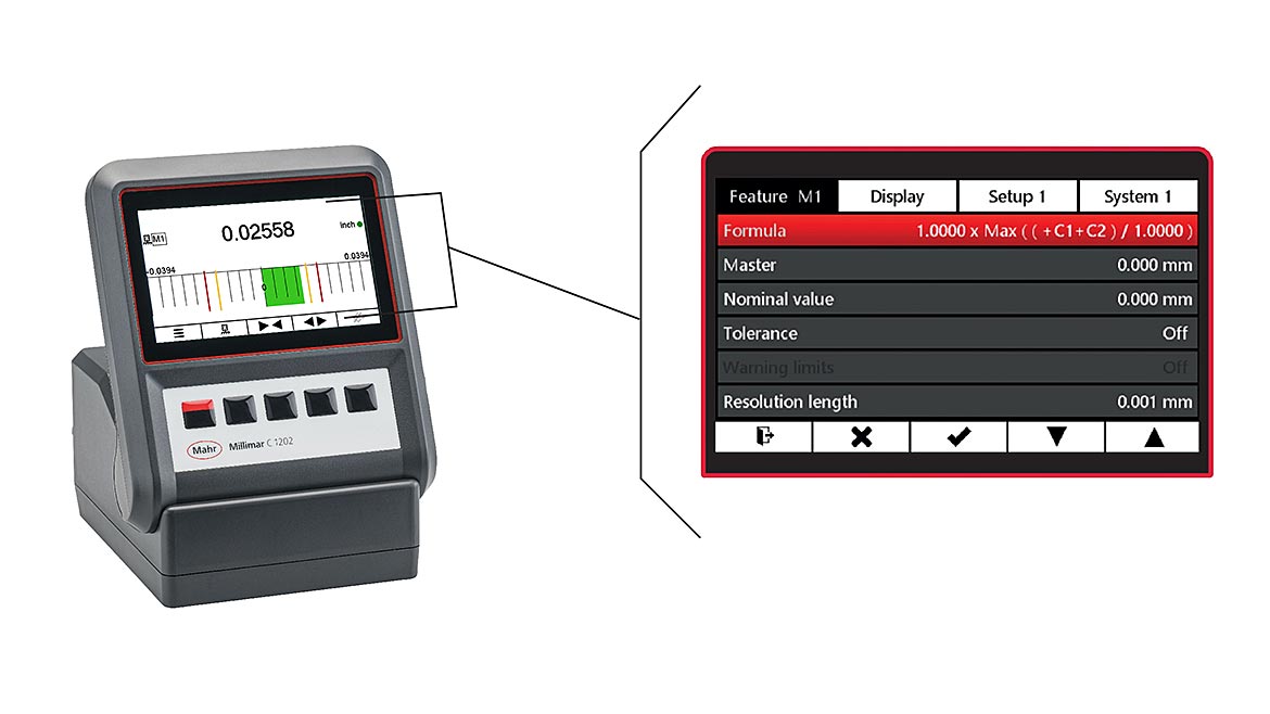
With today’s digital products, using a gage with a master deviation is relatively simple. The certificate may say that the master is within the class, but its actual size is off by +1um. Most digital displays have a procedure for entering the master deviation into the gage setup routine. Once set, whenever the gage is “zeroed,” it will show that actual deviation as seen on the certification. In effect, the operator makes the gage read what the master actually is. If a part is measured at the actual nominal size, it would read 0.0 on the gage.
For this technique to work effectively on the shop floor, operators must keep track of master deviations by gage and ensure that everyone using those gages is aware of it. This can be a fairly extensive training process when hundreds of operators are involved. And there certainly is some chance for error.
Processes that regularly measure and certify the master to its particular size are crucial. The quality department must track this number; users need to know and account for the offset. As this number is likely to change annually, incorporating this long-term process into the gaging routine is essential.
However, these efforts will pay another long-term dividend. Once the shop-wide process of using master deviations is established, the organization can start monitoring changes in the masters. Calibrations from year to year would typically show some wear in size and probably a small amount of change in the form of masters. If, over the course of a year, the size has changed more than 10% of part tolerance—or more than 20% for tighter tolerance parts—something significant has happened to the process, and one may want to question some of the parts that have been measured since the last calibration.
Therefore, changing to a master deviation-based measuring process requires a different process on the floor. Still, it can save significant dollars in master costs and rework in the short run, as well as provide an excellent long-term check on the manufacturing process.
The Master Deviation Philosophy Used Around the World
In the early 20th century, when AGD standards were first developed and later updated, they maintained the “make it to the nominal size” concept. The masters were made to the nominal size, and classes were used to determine how close to the nominal they were. When the master was certified, it was marked with the nominal size and its class, and a separate piece of paper was provided to record the actual deviations from the nominal size.
This is where problems begin when a company decides to use master deviations. The master is marked with the nominal size, but the documentation noting the actual size is stored elsewhere, creating the task of somehow getting the actual size to the end user. In some companies, this is done with a parking pen or sticker attached to the master. It can be a tracking chore as the master gets recertified, and the master deviation size must be updated.
In other countries, the master deviation philosophy is built into the measurement standards. Specifically, DIN standards for master rings and discs are based on master deviations.
In a nutshell, the thought process works like this. The master is made with more emphasis on form (roundness, cylindricity, and surface finish), and the size of the ring comes last. When measured, the nominal size and deviation from the nominal are etched on the ring. Using the previous 10mm master ring example, the ring would be marked 10.000mm with a 2 (in microns) below the 10.000mm marking. This signifies that the nominal size of the ring is 10,000mm, but in reality, the actual size of the ring is 10.002mm.
This makes it much easier to control when using master deviation because:
- The DIN ring includes a certificate showing the nominal and actual size of the ring to keep on file for ISO purposes.
- The DIN ring has the deviation marked on it, allowing the operator to know what it is for use.
- Whenever the DIN master ring gets recertified, it gets marked with the new deviation and provided with a new certificate.
Thus, the master deviation is always available and updated for the user to input into the gaging station. While there certainly are different tolerance grades of DIN master rings, the better classes are similar to AGD XX but inherently include the deviation as part of the ring markings.
In many manufacturing facilities around the world, this DIN marking concept is now second nature, and operators readily understand and employ master deviation on a daily basis. And, of course, they benefit from improved performance and reduced master costs.
There are some physical size differences with DIN rings/discs, but the real variance is in the dimensional tolerancing. Using the visible master deviation, that actual offset is used and not ignored, which is often the case in many shop applications.
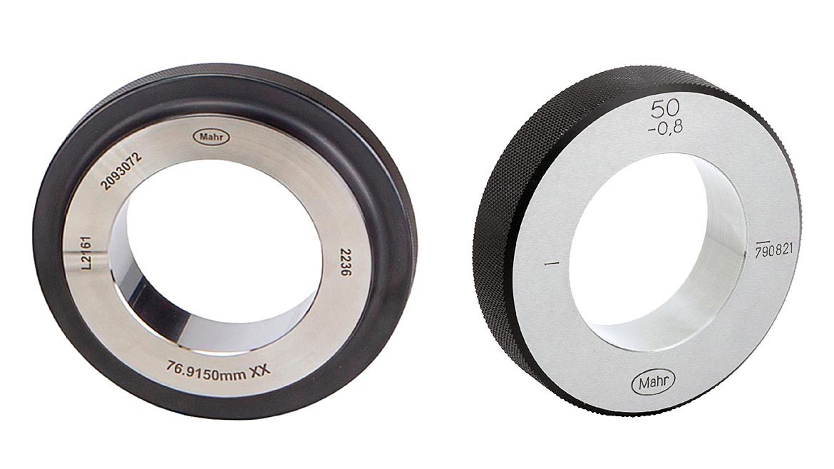
Below is a quick comparison of AGD vs. DIN rings:
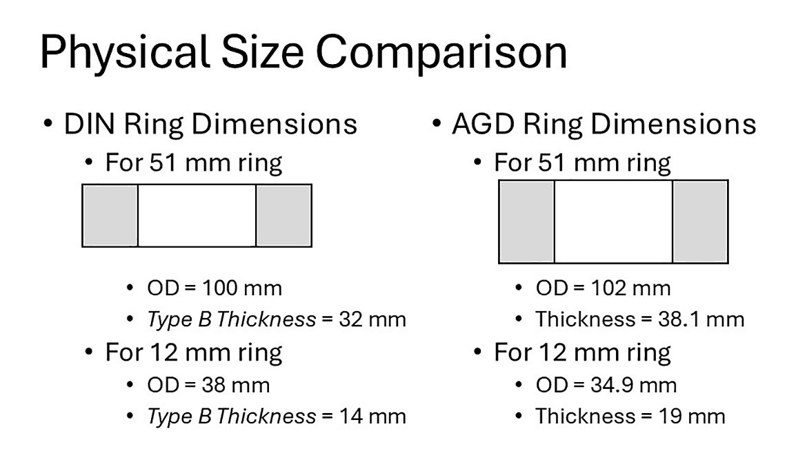
Figure 1 shows a slight difference in the physical size of the ring blanks used for the masters. Not much, but even to the casual user, there’s obviously a difference between the two.
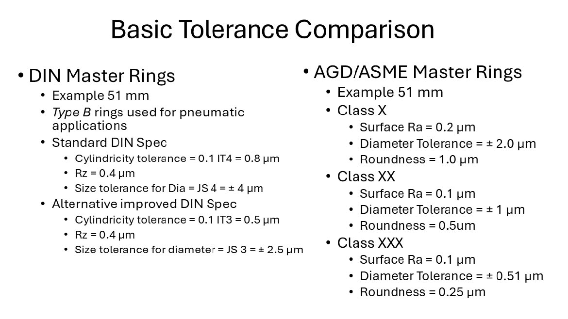
Figure 2. The diameter tolerance for the DIN ring is twice as much as a Class X AGD master ring: for this size, 2,5 µm for the DIN and 1,02 µm for the AGD. But on the other hand, the roundness is tighter in this area. In other words, it’s really not important what the actual size of the hole is: as long as it’s round, the surface finish is good, and the shape is cylindrical, knowing the size and using it as part of the mastering routine can produce the best results from the mastering process.
Looking to the Future
It is evident that the time has come to adopt master deviations as a necessary practice in modern manufacturing processes. With tighter tolerances, it is very easy to implement measurement process improvement. At the same time, it can reduce the initial cost of purchasing more masters than needed and extend the lives of existing masters.
There may be an opportunity for U.S. standards/suppliers to change how rings are marked to include the deviation for easier use.
The concept of changing to use master deviation can be a challenging one. However, with the tolerance requirements being demanded on the shop floor, it is an easy way to realize immediate and improved gaging performance. And in the end, it can pay for itself.
Looking for a reprint of this article?
From high-res PDFs to custom plaques, order your copy today!


