Test & Inspection
X-Ray Nondestructive Testing: What to Know and What to Ask
By knowing the material, thickness, composition, and smallest feature of interest, you give your testing partner the information they need to design an efficient and accurate inspection.
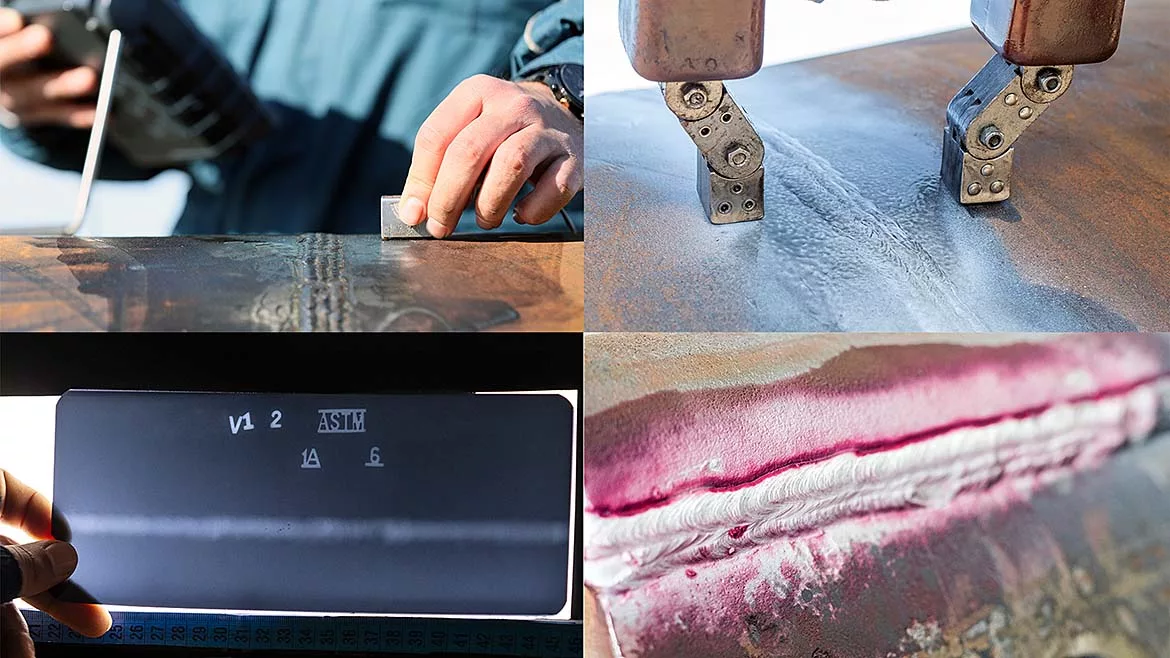
X-ray inspection has long been one of the most trusted methods for inspecting a part without cutting it open. Within the broader field of nondestructive testing (NDT), radiography remains a remarkably flexible tool—able to reveal hidden flaws, confirm weld quality, or verify internal structures that can’t be seen by eye. It’s used everywhere from aerospace and defense to energy, electronics, and manufacturing.
As with any NDT process, success depends on preparation. Before you reach out to a testing provider, it’s worth knowing the details they’ll ask for. Having that information ready makes conversations smoother, quotes more accurate, and results more reliable. Below are a few questions to think through before your first call.
1. What Material Is the Part Made Of?
The starting point in any radiographic evaluation is the material itself. The denser the material, the more energy the X-ray source must generate to penetrate it. That energy is measured in kilovolts (kV).
A thin aluminum or titanium casting might image cleanly at 60-80 kV, while a forged steel housing could need several hundred. Copper alloys, or heavy brass components require even higher settings. Because not every lab operates across the whole energy spectrum—from 160 kV tubes to 9 MeV accelerators—knowing what your part is made of helps determine whether a facility has the correct setup for the job. It also helps them balance exposure, contrast, and detail from the beginning.
(See the reference table below for typical ranges.)
2. How Thick Is the Part?
Once the material is identified, thickness becomes the next factor. The thicker the wall, the more radiation it takes to achieve penetration. That affects both the energy level required and the exposure time.
A slight difference in thickness can have a significant effect on the outcome. Providing accurate part dimensions enables the lab to determine whether a standard X-ray tube will suffice or whether higher-power sources are required. Without that information, a job may need to be reconfigured or repeated later—costing time and money.
3. Is It Made of One Material or Several?
Many modern designs combine different materials—an aluminum housing with a steel insert, or a copper conductor surrounded by insulation, for example. Mixed densities complicate imaging. When the X-ray is strong enough to pass through the denser material, the lighter sections can overexpose, making small details disappear.
If your part includes multiple materials or layers, mention that early. A skilled radiographer can adjust exposure, use filters, or even take multiple images to capture the full range of contrast. That small step often makes the difference between a useful image and one that misses critical information.
4. What’s the Smallest Feature You Need to See?
Every X-ray setup involves tradeoffs between power and resolution. Higher energy allows deeper penetration but can reduce image sharpness. The slightest defect or feature you need to resolve determines which approach makes sense.
- Conventional systems using film or imaging plates generally resolve down to about 0.010 in (254 µm).
- Micro-focus systems, which use focal spots as small as 10 µm and high-resolution detectors, can see details as fine as 0.00008 in (2 µm).
If your work involves microelectronics, additive manufacturing, or intricate aerospace parts, that level of magnification might be necessary. Not every lab has it—so be sure to ask.
Industrial Radiography X-Ray kV Range Chart
This table outlines typical voltage ranges needed to image common engineering materials. Actual requirements vary with density, geometry, and setup, but the values below give a practical starting point for discussion.
| Material | Typical Thickness Range | Recommended kV Range | Notes / Applications |
|---|---|---|---|
| Aluminum (6061, 7075, etc.) | 0.125–0.25 in (3–6 mm) | 40–60 kV | Thin sheet or welds—low energy gives better contrast. |
| 0.25–0.5 in (6–13 mm) | 60–90 kV | Common aircraft components. | |
| 0.5–1.0 in (13–25 mm) | 90–130 kV | Thicker castings and structures. | |
| 1.0–2.0 in (25–50 mm) | 130–160 kV | May require longer exposure times. | |
| Steel (Carbon / Low Alloy) | 0.125–0.25 in (3–6 mm) | 80–120 kV | Sheet welds, small components, pipelines. |
| 0.25–0.5 in (6–13 mm) | 120–180 kV | Common pressure vessel welds. | |
| 0.5–1.0 in (13–25 mm) | 180–250 kV | Standard plate or pipe welds. | |
| 1.0–2.0 in (25–50 mm) | 250–400 kV | Heavy-wall pipe or castings. | |
| Stainless Steel (304, 316) | 0.25–0.5 in (6–13 mm) | 120–200 kV | Slightly higher energy due to density and scatter. |
| 0.5–1.5 in (13–38 mm) | 200–300 kV | Sanitary or process welds. | |
| Titanium (Grades 2–5) | 0.125–0.25 in (3–6 mm) | 80–120 kV | Aerospace sheet and weldments. |
| 0.25–0.5 in (6–13 mm) | 120–160 kV | Good image contrast at moderate power. | |
| 0.5–1.0 in (13–25 mm) | 160–220 kV | Thicker forged parts or castings. | |
| Copper / Nickel Alloys | 0.125–0.5 in (3–13 mm) | 120–200 kV | Electrical or mechanical components. |
| 0.5–1.0 in (13–25 mm) | 200–300 kV | Dense material—requires a stronger source. | |
| Lead / Brass | 0.125–0.5 in (3–13 mm) | 200–400 kV | Shielding, fittings, or heavy castings. |
Reference Guidelines
- Film radiography typically uses 60–320 kV.
- Digital panels and CR systems may operate from 40–450 kV, depending on calibration.
- Steel sections thicker than 2 inches (50 mm) often require a linear accelerator in the 1–6 MeV range.
- In most cases, using the lowest kV that still achieves full penetration produces the best image contrast and sensitivity.
Final Thoughts
Radiography is both an art and a science. The equipment matters, but so does how well the problem is defined before testing begins. By knowing the material, thickness, composition, and smallest feature of interest, you give your testing partner the information they need to design an efficient and accurate inspection.
When both sides come prepared, the process runs more smoothly, images are sharper, and insights are clearer. In the world of nondestructive testing, that’s how you move from simply seeing inside a part to truly understanding its integrity and performance.
Looking for a reprint of this article?
From high-res PDFs to custom plaques, order your copy today!


